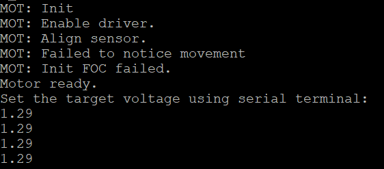
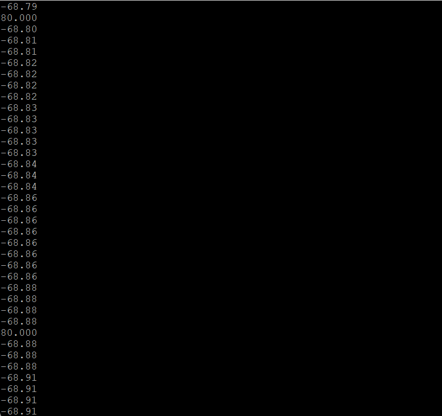
Hello, I am working with a STM32r405 based board and an AS5048 on Arduino IDE. I can get it to work in open loop and the sensor reads correctly, but in closed loop mode it still fails. I put a sensor.getAngle in the main loop and It shows the correct values, but it fails to calibrate and if I skip calibration with hard coded values it just jerks and stays still. I don’t know why the library seems like it cannot use the sensor values. please help.
Code:
{
/**
 * Torque control example using voltage control loop.
 *
 * Most of the low-end BLDC driver boards doesn't have current measurement therefore SimpleFOC offers
 * you a way to control motor torque by setting the voltage to the motor instead hte current.
 *
 * This makes the BLDC motor effectively a DC motor, and you can use it in a same way.
 */
#include <SimpleFOC.h>
#include <Arduino.h>
#include "SPI.h"
//#include <Wire.h>

#define HSE_VALUE 8000000


// from STM Cube-IDE, Clock config
//extern "C"
void SystemClock_Config(void)
{
 RCC_OscInitTypeDef RCC_OscInitStruct = {0};
 RCC_ClkInitTypeDef RCC_ClkInitStruct = {0};
 /** Configure the main internal regulator output voltage
 */
 __HAL_RCC_PWR_CLK_ENABLE();
 __HAL_PWR_VOLTAGESCALING_CONFIG(PWR_REGULATOR_VOLTAGE_SCALE1);
 /** Initializes the RCC Oscillators according to the specified parameters
 * in the RCC_OscInitTypeDef structure.
 */
 RCC_OscInitStruct.OscillatorType = RCC_OSCILLATORTYPE_HSE;
 RCC_OscInitStruct.HSEState = RCC_HSE_ON;
 RCC_OscInitStruct.PLL.PLLState = RCC_PLL_ON;
 RCC_OscInitStruct.PLL.PLLSource = RCC_PLLSOURCE_HSE;
 RCC_OscInitStruct.PLL.PLLM = 4;
 RCC_OscInitStruct.PLL.PLLN = 168;
 RCC_OscInitStruct.PLL.PLLP = RCC_PLLP_DIV2;
 RCC_OscInitStruct.PLL.PLLQ = 4;
 if (HAL_RCC_OscConfig(&RCC_OscInitStruct) != HAL_OK)
 {
   Error_Handler();
 }
 /** Initializes the CPU, AHB and APB buses clocks
 */
 RCC_ClkInitStruct.ClockType = RCC_CLOCKTYPE_HCLK|RCC_CLOCKTYPE_SYSCLK
                             |RCC_CLOCKTYPE_PCLK1|RCC_CLOCKTYPE_PCLK2;
 RCC_ClkInitStruct.SYSCLKSource = RCC_SYSCLKSOURCE_PLLCLK;
 RCC_ClkInitStruct.AHBCLKDivider = RCC_SYSCLK_DIV1;
 RCC_ClkInitStruct.APB1CLKDivider = RCC_HCLK_DIV4;
 RCC_ClkInitStruct.APB2CLKDivider = RCC_HCLK_DIV2;
 if (HAL_RCC_ClockConfig(&RCC_ClkInitStruct, FLASH_LATENCY_5) != HAL_OK)
 {
   Error_Handler();
 }
}

#define PIN_SERIAL1_RX         PA3
#define PIN_SERIAL1_TX         PA2
#define SERIAL_PORT_HARDWARE  Serial2
HardwareSerial Serial2(PIN_SERIAL1_RX, PIN_SERIAL1_TX);

// MagneticSensorSPIConfig_s AS5047P_SPI = {
//   .spi_mode = SPI_MODE1,
//   .clock_speed = 500000,
//  .bit_resolution = 14,
//  .angle_register = 0x3FFF,
//  .data_start_bit = 13,
//  .command_rw_bit = 14,
//  .command_parity_bit = 15
// };

// magnetic sensor instance - SPI
// MagneticSensorSPI sensor = MagneticSensorSPI(AS5147_SPI, 10);
// magnetic sensor instance - I2C
MagneticSensorSPI sensor = MagneticSensorSPI(AS5147_SPI, PA_0);
//MagneticSensorAS5048A sensor(8);
// magnetic sensor instance - analog output
// MagneticSensorAnalog sensor = MagneticSensorAnalog(A1, 14, 1020);

#define ENABLE_PIN PB12
// #define PWMA PC9
// #define PWMB PA8
// #define PWMC PB13
// #define PWMD PB14
// #define PWME PA9
// #define PWMF PB15
#define M0_INH_A PA8
#define M0_INH_B PA9
#define M0_INH_C PA10
#define M0_INL_A PB13
#define M0_INL_B PB14
#define M0_INL_C PB15

// BLDC motor & driver instance
// BLDCMotor motor = BLDCMotor(pole pair number);
BLDCMotor motor = BLDCMotor(7);
// BLDCDriver3PWM driver = BLDCDriver3PWM(pwmA, pwmB, pwmC, Enable(optional));
BLDCDriver6PWM driver = BLDCDriver6PWM(M0_INH_A, M0_INL_A, M0_INH_B, M0_INL_B, M0_INH_C, M0_INL_C, ENABLE_PIN);

// Stepper motor & driver instance
//StepperMotor motor = StepperMotor(50);
//StepperDriver4PWM driver = StepperDriver4PWM(9, 5, 10, 6, 8);

// voltage set point variable
float target_voltage = 0;
// instantiate the commander
Commander command = Commander(Serial2);
void doTarget(char* cmd) { command.scalar(&target_voltage, cmd); }

// void reciveHandle(int Howmany){
//   target_voltage = map((float)Wire.read(), 0, 255, -12, 12);
// }
SPIClass SPI_2(PC12, PC11, PC10);

void setup() {

  Serial2.begin(115200);

  //pinMode(PA0, OUTPUT);

  // SPI.setMISO(PC11);
  // SPI.setMOSI(PC12);
  // SPI.setSCLK(PC10);

  // enable more verbose output for debugging
  // comment out if not needed
  //SimpleFOCDebug::enable(&Serial2);

  // initialise magnetic sensor hardware
  //sensor.spi_mode = SPI_MODE1; // spi mode - OPTIONAL
  //sensor.clock_speed = 1000000; // spi clock frequency - OPTIONAL
  sensor.init(&SPI_2);
  // link the motor to the sensor
  motor.linkSensor(&sensor);

  // power supply voltage
  driver.pwm_frequency = 40000;
  driver.voltage_power_supply = 12;
  driver.voltage_limit = 12;
  driver.init();
  motor.linkDriver(&driver);
  //motor.phase_resistance = 1.5;

  // motor KV rating [rpm/V]
  //motor.KV_rating = 920; // rpm/volt - default not set 920kv ready to sky

  // aligning voltage
  motor.voltage_sensor_align = 0.5;
  // choose FOC modulation (optional)
  //motor.foc_modulation = FOCModulationType::SpaceVectorPWM;
  // set motion control loop to be used
  motor.controller = MotionControlType::torque;

  // comment out if not needed
  motor.useMonitoring(Serial2);

  //motor.zero_electric_angle  = 1.466;
  //motor.sensor_direction = Direction::CW; // CW or CCW
  motor.voltage_limit = 0.5;
  // initialize motor
  motor.init();
  // align sensor and start FOC
  motor.initFOC();

  // add target command T
  command.add('T', doTarget, "target voltage");

  Serial2.println(F("Motor ready."));
  Serial2.println(F("Set the target voltage using serial terminal:"));
  _delay(100);
}

//int pulseWidth = 0;
//int loopCount = 0;
//int v1 = 0;
//int startTime;
//int endTime;
void loop() {
  //startTime = millis();
  // main FOC algorithm function
  // the faster you run this function the better
  // Arduino UNO loop  ~1kHz
  // Bluepill loop ~10kHz
  motor.loopFOC();

  Serial2.println(sensor.getAngle());
  // Motion control function
  // velocity, position or voltage (defined in motor.controller)
  // this function can be run at much lower frequency than loopFOC() function
  // You can also use motor.move() and set the motor.target in the code
  //motor.move(target_voltage);
//  if (loopCount > 25) {
//    pulseWidth = pulseIn(2, HIGH, 20000);
//    //Serial.println(pulseWidth);
//    if(pulseWidth < 500) {
//      v1 = 0;
//    }
//    else {
//      v1 = map(pulseWidth, 500, 2000, -12, 12);
//    }
//    //Serial.println(pulseWidth);
//    motor.move(v1);
//    loopCount = 0;
//  }


  // user communication
  motor.move(target_voltage);
  command.run();
  //loopCount++;
  //endTime = millis();
  //Serial.println(startTime-endTime);
}

}

