I’d like to show you the current draft of the FOC Stepper Driver I designed. I already mentioned a few details in my previous thread, but now I’d like to give a full overview.
Before I go into details, these are the design goals/specifications I’m looking to achieve (ideally, not necessarily with the first revision):
- Suitable for common NEMA 17 stepper motors - more specifically, I’m looking at the 42STH48-2504AH or the similar 42STH48-2504AC
- Step Angle: 1.8°
- Phase Resistance: 1.2 Ω
- Phase Inductance: 1.5 mH
- Rated Phase Current: 2.5 A
- Target application: High-performance 3D printers built using the Klipper firmware
- Ideally, the finished driver would be able to perform on par with common stepper drivers (e.g. TMC2209/TMC5160) in the typical kinematic profiles of 3D printers. When supplied with 48V, I’m looking to achieve speeds of 1600 mm/s with acceleration up to 20000-30000 mm/s^2. With a common configuration of 20T 2GT (2mm pitch) pulleys, this is equivalent to 2400 rpm.
- Ideally, the FOC driver would outperform the regular current chopper drivers in terms of noise and current consumption.
- Motor voltage up to 48V - although I’m likely going to start testing with 24V
At the moment, I’m not sure whether the goals are achievable or if the limitations of stepper FOC (high pole count requiring high encoder resolution) are too restricting.
For the first prototype, I’ve made the following choices:
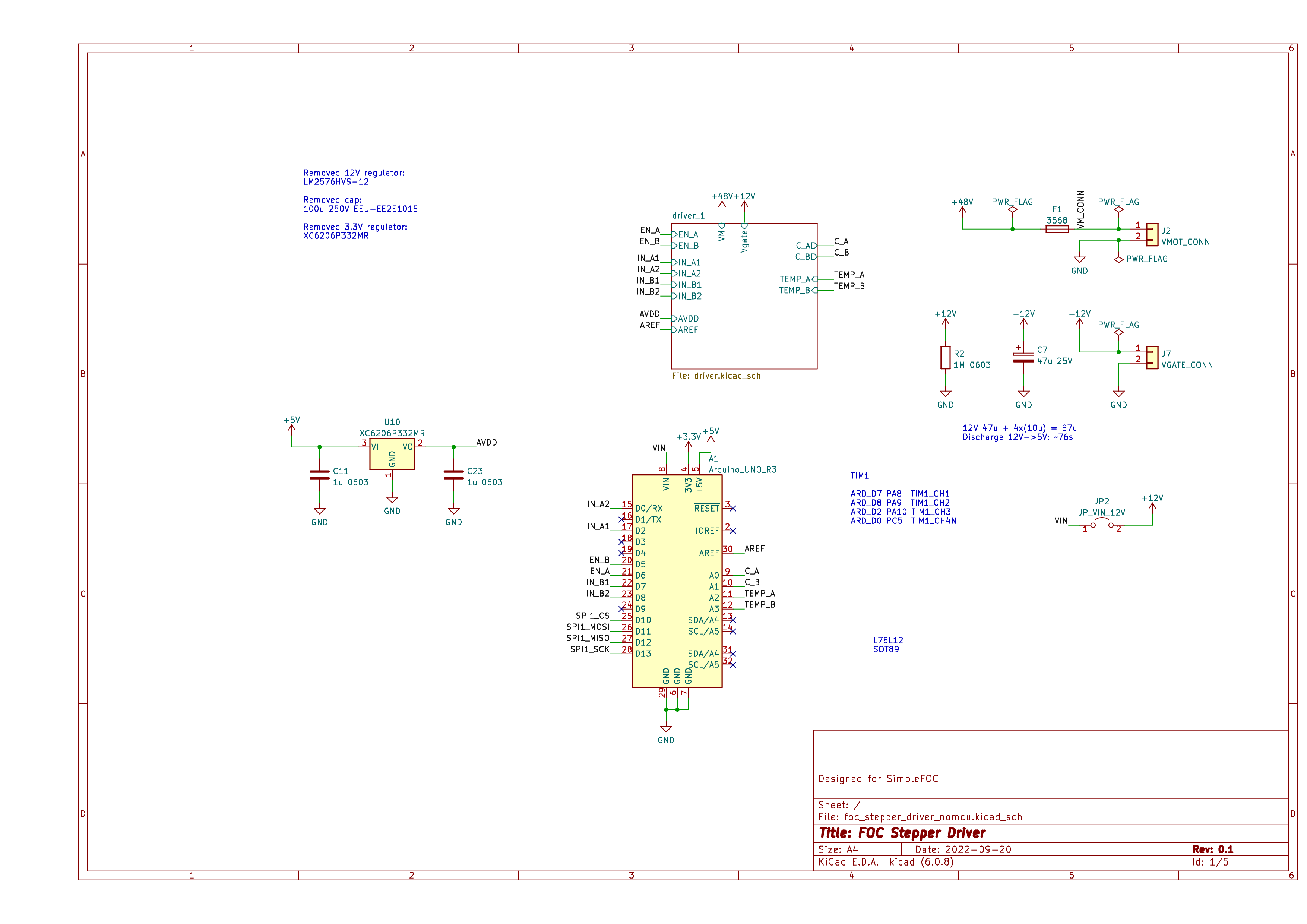
- I’m sticking to the Arduino form factor and won’t integrate a MCU into the board. I have an STM Nucleo-64 board with a STM32G431 I plan to use initially.
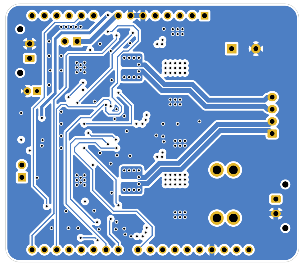
- Four layer design, inner layers used for ground plane and power (48V/12V/3.3V).
- Maximum nominal motor voltage 48V, all components interfacing with motor voltage are rated for 60V or higher to account for any voltage spikes.
- Maximum phase current: 3A
- Nominal 12V gate driver input. I considered integrating a high input voltage buck converter (e.g. XL7005) into the design, but skipped this due to the added complexity. However, it is quite important that the gate driver voltage is always present whenever the motor voltage is present, as I didn’t integrate any pull-downs on the main MOSFET gates for simplicity. Only the gate driver inputs have pull-downs.
- 12V can optionally be connected to the Arduino VIN port
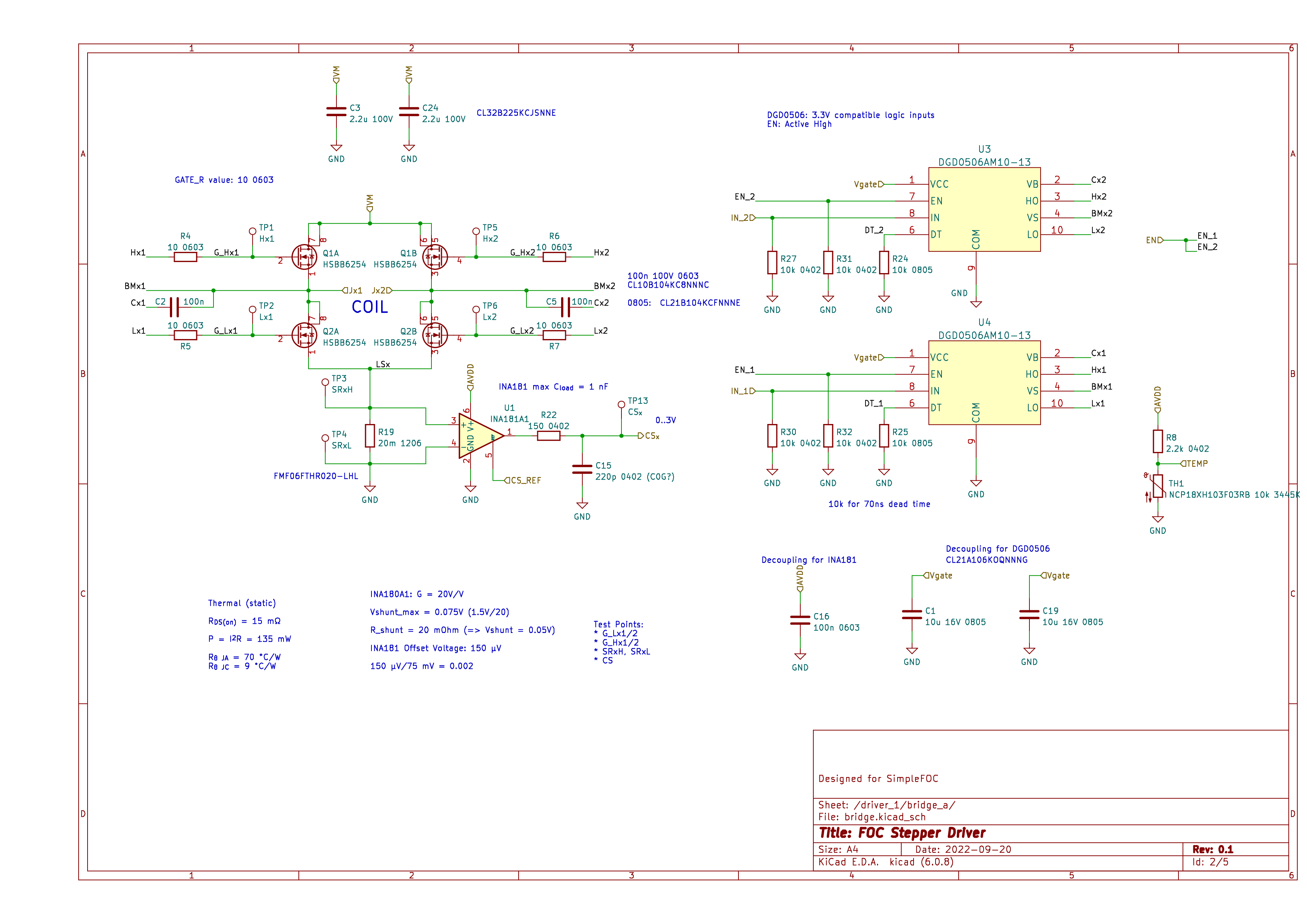
- HSBB6254 dual N-channel MOSFETs, rated for 60V and 20A.
- DGD0506 gate drivers
- Low-side current sensing using INA181A1 shunt amplifiers - these are actually pretty nice as they allow setting a midpoint reference externally
- Keystone 3568 blade fuse holder. Not really necessary for the first prototype, but I saw these on another driver board and liked the fuse form factor.
- Two NTC thermistors for bridge temperature sensing
- On-board 3.3V LDO as an analog supply - used to supply the INA181s and the thermistors. I wasn’t quite sure how noisy the Nucleo-64 3.3V supply might be, and small 3.3V LDOs are cheap.
There are some details I’m still wondering about - I’d appreciate any input on this:
- I’m looking to add some test points to measure the gate voltages, but I’m a little concerned about accidentally shorting stuff on the PCB (since the test points would be rather close to pads and pins carrying high voltage and/or high current).
- I connected the driver PWM inputs to four different channels of TIM1 except for one complementary channel (CH4N) since CH4 is not readily available on the Arduino pins. If I understand correctly this is not critical when using the 4PWM stepper mode (unlike 3PWM/6PWM BLDC mode, where this is important).
- The INA181 datasheet recommends filtering after the amplifier, but at the same time the maximum capacitive load on the INA181’s output is 1 nF. I decided to add a conservative RC filter to the output instead of going for fancier filtering architectures.
- The DGD0506 does not specify a recommended decoupling capacitor. Initially I only had 10 uF caps for each gate driver, then I added another 47uF bulk capacitor. I should probably reduce the decoupling caps to 100 nF or maybe 1uF, but I’m not really sure what value to choose here.
Phew, those were many details - I probably still missed some. Please don’t hesitate to ask for clarification if something is unclear.
I’m looking forward to any thoughts or suggestions!
Schematics
I hope these are sufficiently readable.
Edit: If you open the images in a new tab, they are shown in full resolution, at least for me
Top schematic
Driver
Bulk motor voltage capacitor and bleed resistor.
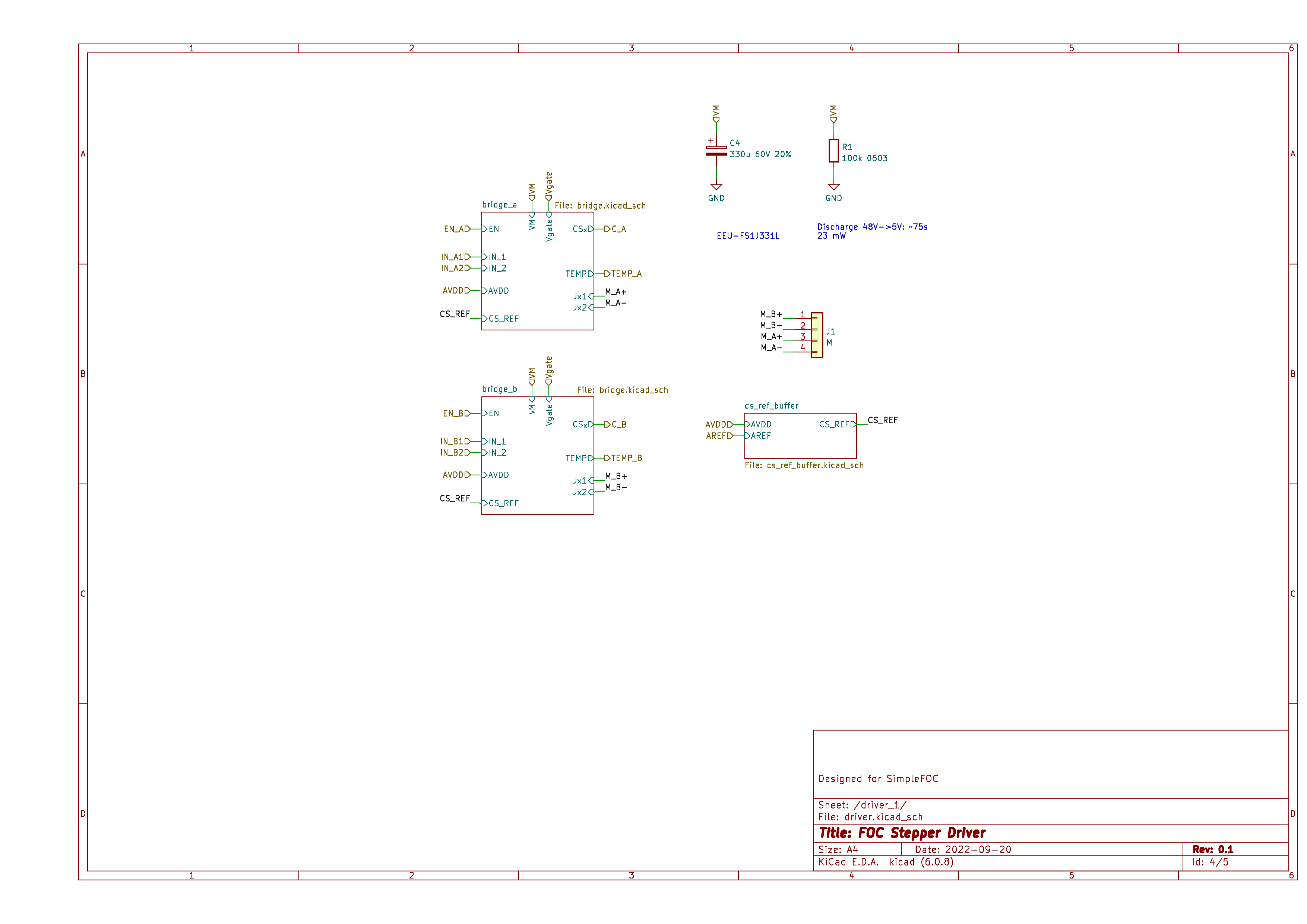
Single Bridge
One of two bridges.
Current Sense reference
Nothing exciting here, just a jumper that allows choosing between a midpoint (1.5V) voltage reference based on an AREF voltage divider or using an external input. A LMV321 opamp acts as a buffer in case the external reference is a high-impedance source.