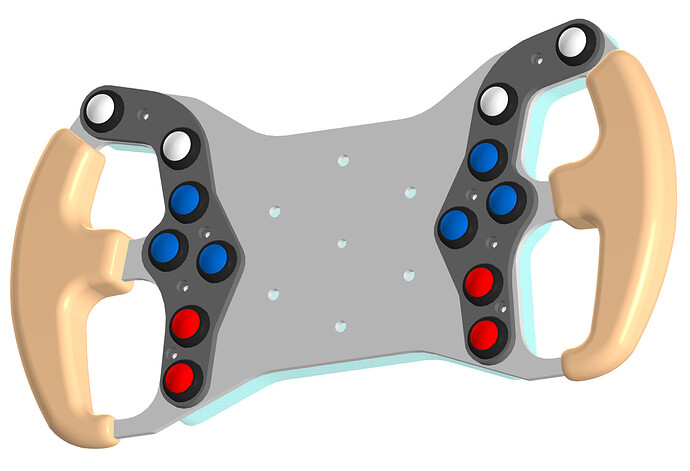
Hello comrades. I had not yet finished with the design of my steering wheel, as there was a wild desire to build a mobile platform. Today I tried a sketch from the example of step direction, for signaling I use the second arduino board. The pulses are applied every 100 microseconds, but the motor does not rotate. Please tell me, what am I doing wrong? By the way, my wife is very glad that I found you guys)))
/**
 * A position control example using step/dir interface to update the motor position
 */

#include <SimpleFOC.h>

// BLDC motor & driver instance
BLDCMotor motor = BLDCMotor(7);
BLDCDriver3PWM driver = BLDCDriver3PWM(9, 10, 11, 8);

// Stepper motor & driver instance
//StepperMotor motor = StepperMotor(50);
//StepperDriver4PWM driver = StepperDriver4PWM(9, 5, 10, 6,  8);

// encoder instance
Encoder encoder = Encoder(2, 3, 1024);
// channel A and B callbacks
void doA() { encoder.handleA(); }
void doB() { encoder.handleB(); }

// StepDirListener( step_pin, dir_pin, counter_to_value)
StepDirListener step_dir = StepDirListener(A4, A5, 2.0f*_PI/200.0);
void onStep() { step_dir.handle(); }

void setup() {

  // initialize encoder sensor hardware
  encoder.init();
  encoder.enableInterrupts(doA, doB);
  // link the motor to the sensor
  motor.linkSensor(&encoder);

  // driver config
  // power supply voltage [V]
  driver.voltage_power_supply = 12;
  driver.init();
  // link the motor and the driver
  motor.linkDriver(&driver);

  // aligning voltage [V]
  motor.voltage_sensor_align = 3;
  // index search velocity [rad/s]
  motor.velocity_index_search = 3;

  // set motion control loop to be used
  motor.controller = MotionControlType::angle;

  // contoller configuration
  // default parameters in defaults.h
  // velocity PI controller parameters
  motor.PID_velocity.P = 0.2f;
  motor.PID_velocity.I = 5;
  motor.PID_velocity.D = 0;
  // default voltage_power_supply
  motor.voltage_limit = 5;
  // jerk control using voltage voltage ramp
  // default value is 300 volts per sec  ~ 0.3V per millisecond
  motor.PID_velocity.output_ramp = 1000;

  // velocity low pass filtering time constant
  motor.LPF_velocity.Tf = 0.01f;

  // angle P controller
  motor.P_angle.P = 10;
  //  maximal velocity of the position control
  motor.velocity_limit = 100;

  // use monitoring with serial
  Serial.begin(115200);
  // comment out if not needed
  motor.useMonitoring(Serial);

  // initialize motor
  motor.init();
  // align encoder and start FOC
  motor.initFOC();

  // init step and dir pins
  step_dir.init();
  // enable interrupts
  step_dir.enableInterrupt(onStep);
  // attach the variable to be updated on each step (optional)
  // the same can be done asynchronously by caling motor.move(step_dir.getValue());
  step_dir.attach(&motor.target);

  Serial.println(F("Motor ready."));
  Serial.println(F("Listening to step/dir commands!"));
  _delay(1000);
}

void loop() {

  // main FOC algorithm function
  motor.loopFOC();

  // Motion control function
  motor.move(step_dir.getValue());
}