Speed limited to ~400 rad/s with low resistance, high K motors

Hello, I’m having trouble getting some low-resistance “quadcoptor” type motors to spin past ~4K RPM. The motors work wonderfully, efficiently, and silently up to about 2K RPM, then after that start to use ridiculous amounts of power, topping out at ~4KRPM and consuming ~100W!

commanded_target_voltage, speed(rad/s), power consumed
0.1 - 28, 0.6W
0.5 - 103, 1.7W
1.0 - 356, 32W
1.5 - 439, 96W

-The motors work past 20K rpm with a cheap commercial ESC, consuming around 35W at 20KRPM
-The AS5048A sensor can accurately read RPMs past ~20KRPM (I tested this by leaving simpleFOC running with the monitor whilest hooking the 3 power phases to an ESC and cranking it up to 20KRPM)
-I tried different modulation types, motor downsampleing and anything else I could think of… NOthing works.

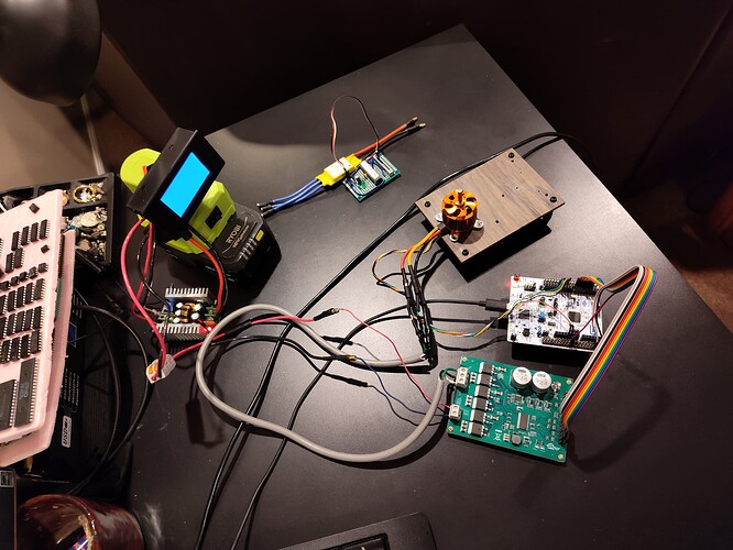
Motor: D3536, K=~2000, resistance=0.1Ohm, unloaded
Sensor: AS5048A
Driver: DRV8301 board, 3 PWM mode
Controller: NUCLEO G431RB
Algorithm: SimpleFOC, Torque mode, voltage feedback

/*

*/

#include <SimpleFOC.h>
#include "DRV8301.h"


MagneticSensorSPI sensor = MagneticSensorSPI(AS5147_SPI, 10); // MOSI=11, MISO=12, CSK=13.

DRV8301 gate_driver = DRV8301(3, 4, 5, 2, 6, 7); // MOSI, MISO, SCLK, CS, EN_GATE, FAULT
BLDCMotor motor = BLDCMotor(7); // 2208

BLDCDriver3PWM driver = BLDCDriver3PWM(PC0, PC1, PC2);


Commander command = Commander(Serial);
// void doMotor(char* cmd) { command.motor(&motor, cmd); }
void doTarget(char* cmd) {command.scalar(&motor.target, cmd);}
void doLimit(char* cmd) {command.scalar(&motor.voltage_limit, cmd);}
void doMotor(char* cmd) { command.motor(&motor, cmd); }

char msgbuf[256];

void setup() {

  Serial.begin(921600); // WARNING: low value like 115200 cause distorted FOC
  // for timer analysis
  //SimpleFOCDebug::enable(&Serial);
  //delay(5000);
  Serial.printf("enter setup...\n");


  sensor.init();
  // link the motor to the sensor
  motor.linkSensor(&sensor);

  // driver config
  // power supply voltage [V]
  driver.voltage_power_supply = 18;
  driver.voltage_limit = 4;
  driver.init();
  // configure the DRV8301
  gate_driver.begin(PWM_INPUT_MODE_3PWM, 1); // no OCP
  _delay(100);
  int reg1, reg2, reg3, reg4, fault;
  gate_driver.get_regs(&reg1, &reg2, &reg3, &reg4);
  fault = gate_driver.is_fault();
  sprintf(msgbuf, "DRV8301: fault=%x, STATREG1=0x%.4x, STATREG2=0x%.4x, CTRLREG1=0x%.4x, CTRLREG2=0x%.4x", fault, reg1, reg2, reg3, reg4);
  Serial.println(msgbuf);

  // link driver
  motor.linkDriver(&driver);
  // link current sense and the driver
  motor.voltage_sensor_align = 0.5;

  //motor.controller = MotionControlType::torque;
  motor.controller = MotionControlType::torque;
  // default voltage_power_supply
  motor.voltage_limit = 2;
  motor.current_limit = 1000;
  motor.velocity_limit = 100;

  // contoller configuration based on the controll type
  motor.PID_velocity.P = 0.1;
  motor.PID_velocity.I = 1.0;
  motor.PID_velocity.D = 0.0;
  motor.PID_velocity.output_ramp = 1000.0;
  motor.PID_velocity.limit = 1000.0;
  motor.LPF_velocity.Tf = 0.1;
// angle loop controller
  motor.P_angle.P = 30;
  motor.motion_downsample = 10.0;
  // set the inital target value
  motor.target = 0;
//  Serial.begin(115200); // WARNING: low value like 115200 cause distorted FOC
  // comment out if not needed
  motor.useMonitoring(Serial);
  //motor.monitor_downsample = 0; // disable intially
  motor.monitor_variables = _MON_TARGET | _MON_VOLT_Q | _MON_VOLT_D | _MON_CURR_Q | _MON_CURR_D | _MON_VEL | _MON_ANGLE;  // monitor target velocity and angle
  //motor.foc_modulation = SpaceVectorPWM;
  // initialise motor
  motor.init();
  // align encoder and start FOC
  motor.initFOC();

  // subscribe motor to the commander
  command.add('T', doTarget, "target");  // ssss space
  command.add('L', doLimit, "voltage limit");
  command.add('M',doMotor,"motor");

  Serial.printf("setup complete...\n");
  _delay(1000);

}

void loop() {

  // iterative setting FOC phase voltage
  motor.loopFOC();
  // iterative function setting the outter loop target
  motor.move();
  // motor monitoring
  motor.monitor();
  // user communication
  command.run();
}
Have you tried the lag compensation ?
And please reach the other discussions about speed.

Thanks I’ll try that and report back.

Would running in current feedback help with this?

Yes that’s what the d current PID does

This is not unexpected. The cheap ESC is no doubt doing 6-step commutation, which is a lot less computationally intensive, and can reach higher speeds.

If you provide the other parameters to the motor constructor (resistance, KV, inductance) the FOC loop can do more, as @Candas1 has mentioned. It can compensate for BEMF and lag.

Yeah, it definately could help, but on the other hand it is also more computation, so a little slower loop times. You’ll have to test out which is better.

Using SPI will ultimately limit your performance. Normally its not a problem, but when you’re trying to go 20kRPM…
Consider using the STM32HWEncoder class we have in the drivers repository, with the AB interface of your encoder. This has 0-overhead on the MCU side, and also no lag on the MCU side due to communications. You’ll have only the sensor lag itself, which is quite small.

Some quick, naive calculations:

20kRPM on a 7PP motor is 140kERPM, or 2333.33 electrical revolutions per second.
If you were doing 6-step commutation, you’d need (as the name says) 6 steps or iterations per electrical revolution. So 6-step would need your main loop to be going at a speed of 14kHz to reach 20kRPM.

Using sine commutation, you need more steps per electrical revolution: perhaps 12 would be sufficient, but more would be better - so for example 20 iterations per electrical revolution would imply 46.6kRPM that your main loop has to reach.

Of course it does not make sense to update the PWM any faster than the PWM frequency, updates that occur more often would simply be ignored as the PWM hardware can only output one duty cycle per period.
Also, to properly set a voltage you need more than 1 PWM period at the same duty cycle, or else the motor never properly sees this voltage. Infineon recommends 10 cycles per PWM value, but this would clearly be hard to achieve in this scenario.
If we settle on 2 cycles per voltage set, you’d need a PWM frequency of about 94kHz.

So the implication of 20kRPM with FOC control is:

  • you’d need to output 2.3k eRPM in terms of electrical revolutions per second
  • you’d want 46.6kHz loopFOC iteration speed or more to do so
  • you’d need 94kHz PWM frequency, and this would still be low bandwidth for the PWM output
  • you’d need a sensor that can update at 46.6kHz (ideally twice that)

I think you’ve used the library enough to understand that these are challenging goals.

To reach such speeds with FOC control there are space-vector modulation schemes which only use discrete switching (not PWM). SimpleFOC does not support this yet, but this would be one way to get more speed while maintaining field oriented control, and not have such high demands on the hardware.

Another thing you could try is our 6-step trapezoidal commutation modes - it would be a small modification to make it not use PWM… then you could try starting the motor with FOC control, for good torque and efficiency at slow speeds, and switching over to trapezoidal for the high RPMs…

And another note: you can see from above calculations the massive impact the PP of the motor has in terms of demands to the system performance:

if you go from a 7PP motor to one with only 2PP, you could divide all those numbers by 3.5 - suddenly it becomes much more possible to achieve FOC control at this high speed…

Thanks for this very useful information…

I wasn’t aware you had non-FOC 6-step control within the simpleFOC portfolio. Can you point me to some information? (I searched the docs on the website and didn’t see anything). Does your 6-step support sensorless? (IME, this is the most complex part of implementing a 6-step commutator)

And why would I not want to use PWM (sorry I’m probably missing something here)

We support trapezoidal commutation as a modulation scheme.

BLDCMotor | Arduino-FOC , Step 5.1 PWM Modulation type

No, this would need voltage sensing (or zero crossing detection) which SimpleFOC does not at the moment support. It’s on the roadmap, but since our main focus is FOC, the BEMF sensing is lower priority.
So the trapezoidal commutation is still driven by the position sensor.

See my post above. You can’t run the loop faster than the PWM frequency, and ideally the PWM frequency should be several times higher than the loopFOC frequency.
I estimated above you’d need 46kHz loopFOC frequency to reach 20kRPM, so that implies a very high PWM frequency.
But high PWM frequencies are very demanding on the driver stage. If you have one that can handle 100kHz or 150kHz, then go for it! But otherwise you’d be looking for ways to have high loopFOC frequency but less switching events… one way to reduce them would be to switch in 6-step pattern with no PWM.

Ok I first need to understand where my limitation is, but you’ve given me alot of ideas to try, Thanks! I’ll report back with some results.