But now there is something else I don’t understand, probably I am doing a mistake somewhere.
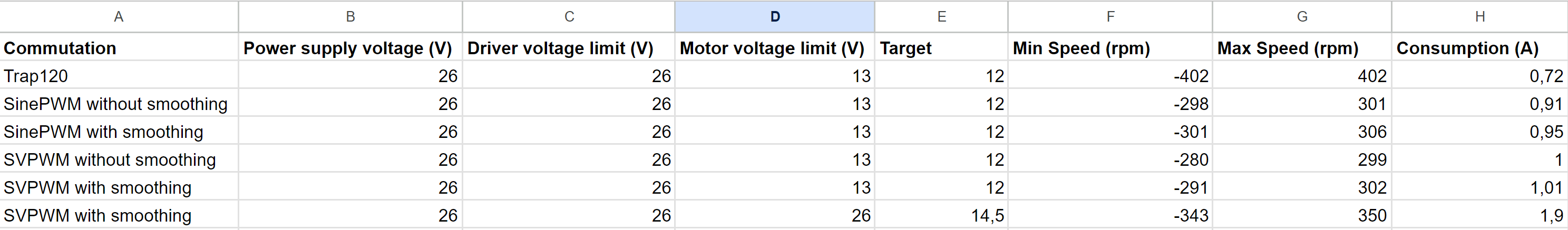
I initially started to test the hoverboard controller with my gd32 driver code using trapezoidal120.
SinePWM seemed more silent but much slower, I thought it had to do with the missing smoothing.
Now SinePWM with smoothing is even more silent but is still much slower than trapezoidal.
And it’s all consuming more than trapezoidal while being slower ?
During my tests driver.voltage_power_supply = driver.voltage_limit.
I am increasing the target until I feel it’s saturating.
15/16 KV seems correct for a hoverboard motor.
Any ideas are welcome.
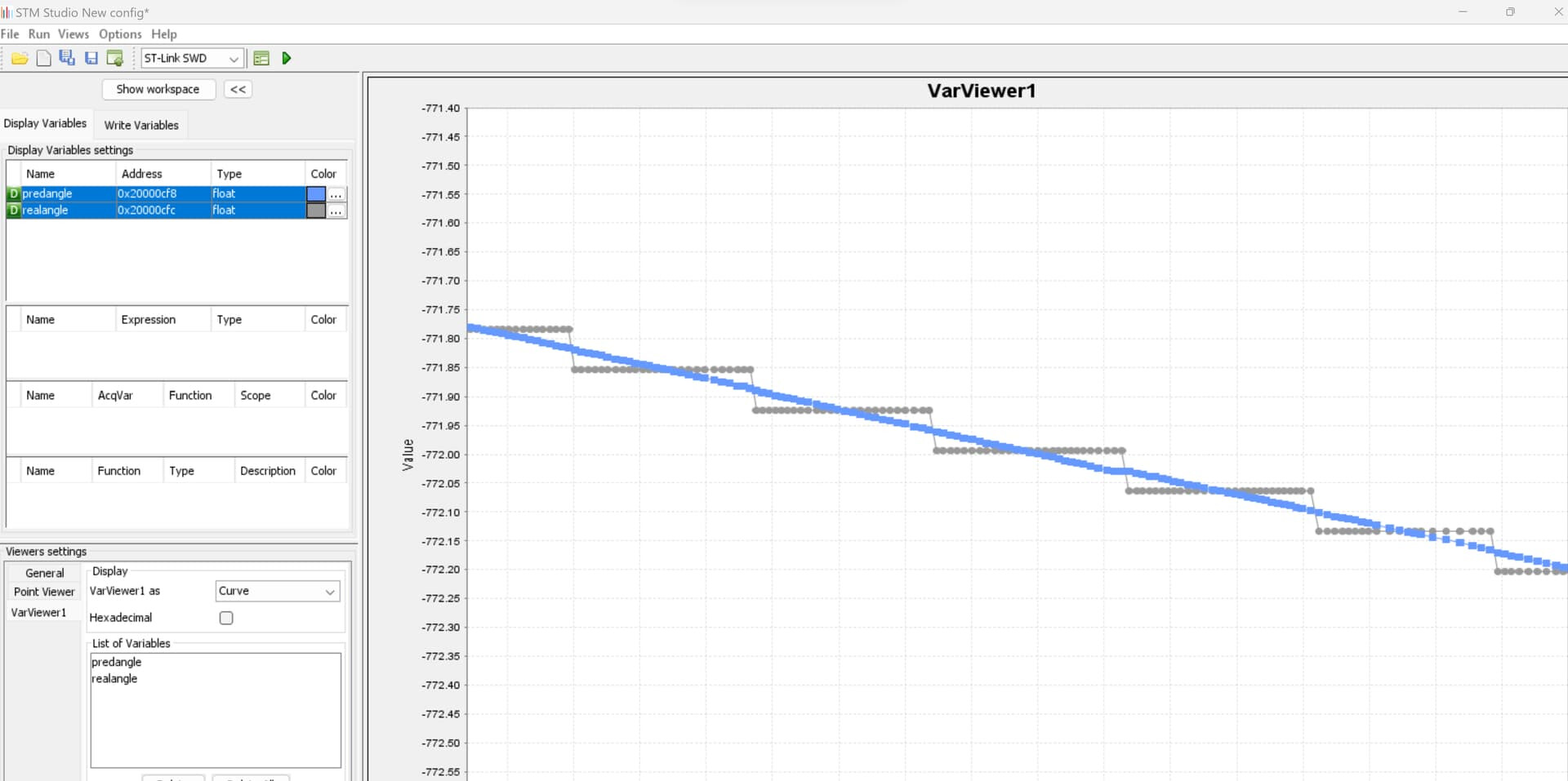
I mentioned this in our PM conversation, but for others reading, the sign inversion most likely means that velocity and phase_correction need to be multiplied by motor.sensor_direction when performing the angle prediction.
The speed chart is interesting. SinePWM without smoothing should produce more or less the same output as trapezoid120, because the electrical angle only changes when the hall state changes. Although trapezoid does have those driver->setPhaseState calls to disable the third phase. Maybe that’s what makes the difference?
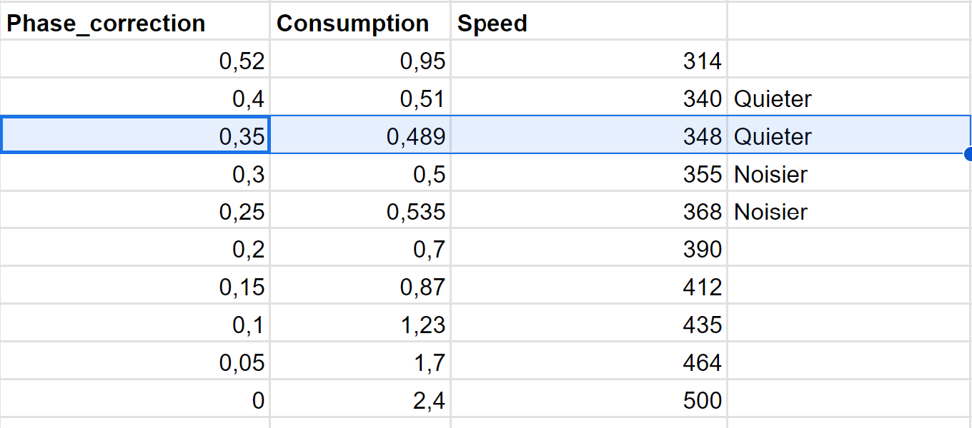
If you want to run another test, I’m curious to see what you get with SmoothingSensor.phase_correction = 0. I thought it would cause field weakening and excessively high speed, but maybe it’s the opposite and un-smoothed sine has the phase shifted somehow, causing it to spin too slow and with poor efficiency?
0,52 should be Pi/6.
0,35 is the sweet spot, it’s quiet and faster than before ( still slower than trapezoidal), and consumes less.
Then from 0,3 to 0,25 it gets a bit noisier, but it’s not due to pitch/speed.
From 0,20 it’s clearly phase advance/field weakening.
No it’s worse than that. Sorry for all the spam.
Using 1.92 as zero_electrical_angle instead of 2.09 was working in one direction, but making things worse in the other direction. I had to apply the opposite shift in the other direction to get the same effect (2.26).
But it works in both directions when I only shift the phase_correction from 0.52 to 0.35.
And interestingly, that 0.35 phase correction is right only at maximum target.
The sweet spot moves from 0.52 to 0.35 as the target increases.
Am I rediscovering the Maximum Torque per Ampere concept lol
[EDIT] Hmm I knew I saw this somewhere, I only found it now. Maybe this will help
Nice, so it looks like phase correction around 0.17 should give similar RPM and current as trapezoid120, so it is only an effective phase difference and nothing fundamentally different about trapezoid mode… and means that trapezoid may be doing some undesirable field weakening, so that should be investigated at some point.
I had to manually adjust the zero angle on mine too (I just change it until max speed is the same in both directions), but I thought it was only due to the stator being rotated a few degrees relative to the sensors on the motor I was testing with (machining error).
Were you restarting and running the auto-calibration for each test in post #26? Given the random variation in min/max speeds regardless of smoothing enabled or not, I’m starting to think the auto-calibration doesn’t work well for hall sensors, giving a random value within ±30 degrees of where it should be rather than finding the exact center of the hall state or transition point between hall states (I’m not sure which it should be).
@dekutree64 I think your interpolation is totally fine, and the value of the phase_correction is also fine.
I first thought the zero angle was a problem but min/max speeds are pretty close.
The problem is not the rotor position, your interpolation estimates it well.
The problem is that as the speed increases, the target vector is not at 90 degrees anymore.
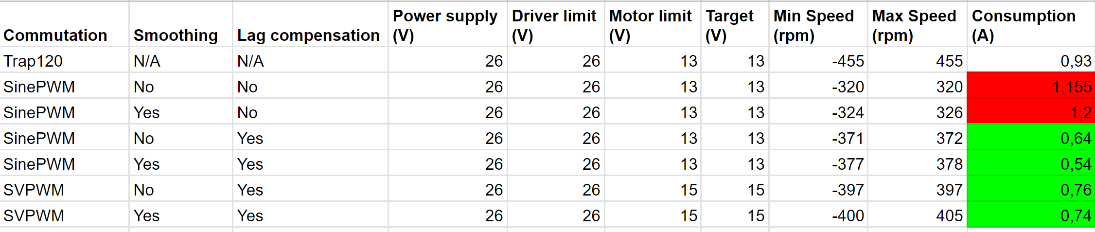
I did a quick test adding the inductance parameter for lag compensation and it was promising.
I will update the table I shared earlier with the different commutations/speed/consumption.
It’s true that the current calibration is not optimal for hall sensors, but I am happy to help with this if you are interested. Having the hall state start/middle/end will also help having a smoother velocity thus a better velocity control.
[EDIT]
SinePWM and SVPWM are much quieter with your extrapolation, and it only slighty increases the speed so phase_correction is ok, no field weakening.
With the lag compensation, consumption is divided by 2 with a higher speed.
SVPWM is faster than SinePWM as you can use a higher voltage limit and target, but still slower than trap120.
I haven’t collected the consumption in both directions, but although the speed is close, there are gaps in consumption.
I probably need to tweak the zero_electrical_angle as I kept the value from the calibration. The inductance parameter could also not be optimal.
Hi,
now that the smoothingSensor is back in focus, I’d like to ask a few questions:
In the beginning it was about PWM sensor smoothing, but later it was about (linear or digital?) hall sensors…
What sensor types are supported now?
Is it included in sFOC 2.3? There don’t seem to be any examples?
[That’s an indirect hint, that some included stone-age examples could use a face lift…but that’s OT]
the dead point in my application is most visible at slow RPM.
Is there a way to tune smoothing for low RPM?
Please let me know if there’s a summary of all that in the docs.
of course at the moment these things are still on the dev branch.
If/when SmoothingSensor becomes so stable that everyone wants and uses it we’ll move it to the main repository. But for the moment, it is part of the more “experimental” code in the drivers library.
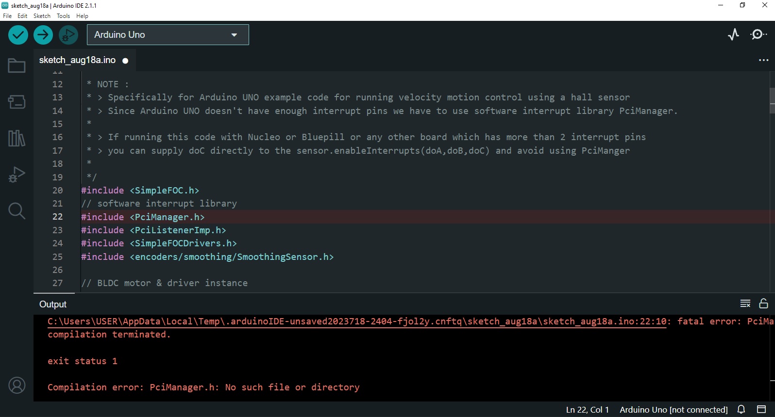
Just out of curiosity I tried to compile the example for an UNO, halfway expecting the code to be too big. But I already stumbled over the Pci_Manager?
It will work with any sensor, but is meaningless on anything with high resolution and fast communication. Assuming you’re referring to janosh85’s thread, he is using digital halls now and therefore it may be helpful.
Yeah, writing documentation is not one of my strong points. And I have minimal hardware to test on, so the examples are mostly copy/paste with the few relevant lines added to show the proper usage pattern.
I always get that Pci_Manager error too, but figured it was just a problem with my environment. I never really looked into it.
Increasing the velocity filter constant can help extend the low end. At least with hall sensors, the motor tends to move in steps at low speed, so the velocity alternates between high and low. By filtering it, you get a more constant velocity reading despite the jerky motion, which results in a smoothly increasing predicted angle, which drives the motor to produce smoother true velocity, creating a happy feedback loop.
But for very low speed, I need to try again at the pseudo-open-loop mode.
No, the version on github uses references rather than pointers like the original from the thread. I matched it to the style of CalibratedSensor because it was there first.
Thanks for the clarifications… I can be a smarta$$ sometimes
Turns out, the Pci_manager is a separate library. I just installed V2.1.4
Now I run into smoothingSensor.h not found.
Guess I have to use the sFOC_driver release of the dev-branch …although it is also labelled V1.0.4 ?
Even with #include <encoders/smoothing/SmoothingSensor.h>, not just #include <SmoothingSensor.h>? Make sure the file is actually there on your hard drive. It should be a separate library Arduino-FOC-Drivers, not in the main Arduino-FOC folder.
I was going to give this a spin soon. I seem to recall that this was now in the main branch, so no need to use the dev branch?
So I include smoothingsensor.h as mentioned above, instantiate the hall sensors in the usual way (maybe give them a test or do the motor init first) and then instantiate the smoothingsensor, feeding it the hall sensor object. Then feed the motor object the smoothingsensor object so it uses that instead of using the hall object directly. Do I need to tell smoothingsensor the time constant for the filter or something?
Hm. Seems like I might encounter difficulty with the motor initialization routine, where it detects the pinouts and orientation of the hall sensors if it was trying to use the smoothingsensor object for that. I can probably skip that part though. I think my motor probably has well aligned hall sensors and I just gotta make sure I don’t get the wiring wrong.
That is correct. SmoothingSensor doesn’t have any filter constants, but you do need to set phase_correction = -_PI_6 for hall sensors. And it doesn’t have any state variables that need continuous updating, so you can call motor.linkSensor at any time to switch between using the HallSensor directly and going through the SmoothingSensor.
I don’t think it will interfere with calibration since the motor velocity should be zero at the time. But the calibration procedure doesn’t really work for hall sensors anyway unless you’re using trapezoid120 modulation. You have to manually tune the zero_electric_angle until top speed is the same in both directions.
I did that with hoverboard motors under no_load condition and it worked fine, but will that work with a fan?
Maybe @Anthony_Douglas has to cover the blades to avoid airflow…
For a fan it would depend on the type - many operate in one direction only and have their design optimized for pushing air one way. Others are bidirectional and designed symmetrically…
As an alternative to tuning the zero by going both directions you can also tune it going only one direction and watching for minimum current, I guess.