First, and I wish I would have included this in my original post, I think this community and the support from everyone is extremely helpful and is really appreciated!
I did some more reading after posting, and I saw a posting about the solder pad configuration:
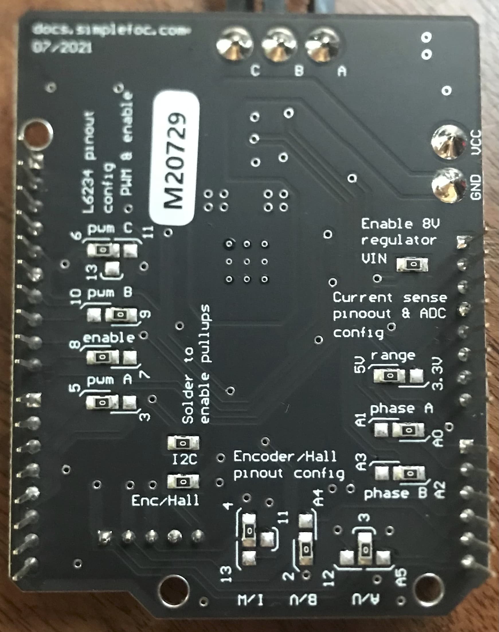
and it looks to me (see attached image)
like the board i received is configured as suggested, so i understand the BLDCDriver3PWM pins set to (9,5,6,8)… i hope i’m understanding that correctly
i reset the DIP settings in the AMT103_V to (0,0,0,0) which corresponds to 2048 PPR and re-ran the SimpleFOC library example codes.
the encoder_example works fine and shows positions ±6.28 with a full turn in each direction
the open_loop_velocity_example appears to run correctly
the open_loop_position_example appears to run correctly
the torque example current_control gets me a “too big to load” error for my arduino R3
the torque example voltage_control appears to partially work, but seems unstable with motor vibrations and reversals of direction
my code for the closed-loop example for angle_control is included below. when i run it, the motor starts turning on its own, if i set a target angle it will settle into a large and rough oscillation around that value, and sometimes that mode then breaks out into a constant rotation, so it appears that it’s trying to work, but has an instability…
i measured the resistance between the three phase leads and got 10.7, 9.9, and 9.2 ohms… i seem to recall those should all be equal???
thanks for the help!
/**
*
- Position/angle motion control example
- Steps:
-
- Configure the motor and encoder
-
- Run the code
-
- Set the target angle (in radians) from serial terminal
- NOTE :
-
Arduino UNO example code for running velocity motion control using an encoder with index significantly
-
Since Arduino UNO doesn’t have enough interrupt pins we have to use software interrupt library PciManager.
-
If running this code with Nucleo or Bluepill or any other board which has more than 2 interrupt pins
-
you can supply doIndex directly to the encoder.enableInterrupts(doA,doB,doIndex) and avoid using PciManger
-
If you don’t want to use index pin initialize the encoder class without index pin number:
-
For example:
-
- Encoder encoder = Encoder(2, 3, 8192);
-
and initialize interrupts like this:
-
- encoder.enableInterrupts(doA,doB)
- Check the docs.simplefoc.com for more info about the possible encoder configuration.
*/
#include <SimpleFOC.h>
// BLDC motor & driver instance
BLDCMotor motor = BLDCMotor(8);
BLDCDriver3PWM driver = BLDCDriver3PWM(9, 5, 6, 8);
// Stepper motor & driver instance
//StepperMotor motor = StepperMotor(50);
//StepperDriver4PWM driver = StepperDriver4PWM(9, 5, 10, 6, 8);
// encoder instance
Encoder encoder = Encoder(2, 3, 2048);
// Interrupt routine intialisation
// channel A and B callbacks
void doA(){encoder.handleA();}
void doB(){encoder.handleB();}
// angle set point variable
float target_angle = 0;
// instantiate the commander
Commander command = Commander(Serial);
void doTarget(char* cmd) { command.scalar(&target_angle, cmd); }
void setup() {
// initialize encoder sensor hardware
encoder.init();
encoder.enableInterrupts(doA, doB);
// link the motor to the sensor
motor.linkSensor(&encoder);
// driver config
// power supply voltage [V]
driver.voltage_power_supply = 7.4;
driver.init();
// link the motor and the driver
motor.linkDriver(&driver);
// aligning voltage [V]
motor.voltage_sensor_align = 3;
// set motion control loop to be used
motor.controller = MotionControlType::angle;
// contoller configuration
// default parameters in defaults.h
// velocity PI controller parameters
motor.PID_velocity.P = 0.2f;
motor.PID_velocity.I = 20;
motor.PID_velocity.D = 0;
// default voltage_power_supply
motor.voltage_limit = 6;
// jerk control using voltage voltage ramp
// default value is 300 volts per sec ~ 0.3V per millisecond
motor.PID_velocity.output_ramp = 1000;
// velocity low pass filtering time constant
motor.LPF_velocity.Tf = 0.01f;
// angle P controller
motor.P_angle.P = 20;
// maximal velocity of the position control
motor.velocity_limit = 4;
// use monitoring with serial
Serial.begin(115200);
// comment out if not needed
motor.useMonitoring(Serial);
// initialize motor
motor.init();
// align encoder and start FOC
motor.initFOC();
// add target command T
command.add(‘T’, doTarget, “target angle”);
Serial.println(F(“Motor ready.”));
Serial.println(F(“Set the target angle using serial terminal:”));
_delay(1000);
}
void loop() {
// main FOC algorithm function
// the faster you run this function the better
// Arduino UNO loop ~1kHz
// Bluepill loop ~10kHz
motor.loopFOC();
// Motion control function
// velocity, position or voltage (defined in motor.controller)
// this function can be run at much lower frequency than loopFOC() function
// You can also use motor.move() and set the motor.target in the code
motor.move(target_angle);
// function intended to be used with serial plotter to monitor motor variables
// significantly slowing the execution down!!!
// motor.monitor();
// user communication
command.run();
}