With a lot of help of @David_Gonzalez, Arduino SimpleFOClibrary now supports the ESP32 boards.
If you are interested in using the library with the ESP32 visit the supported hardware docs to see how to install the support package. It is very simple.
I am looking forward to hearing your impressions, ESP boards are really awesome and they are a great match for this library.
Let me know if you have any troubles running the code!
Antun
I used the new 1.4.1 version of SimpleFOC with my esp32 last night, it worked great!
I’ve tested it with i2c AS5600 magnetic encoder and 2804 gimbal motor using voltage, velocity and position control. Some minor speed wobbles on velocity control (even at higher speeds) but that could well be my PI tuning.
It looks well implemented. Thanks @David_Gonzalez and @Antun_Skuric. This is helping me learn loads! It would be interesting if anyone could get a single esp32 to control 4 motors. Looks like the code is setup ready to support it.
Hi, I’m trying this library on different microcontrollers, and when using esp32 I’ve found some issue when resetting and entering in a reset loop. Sometimes it lasts until I change the initial position of the motor, sometimes it is random…
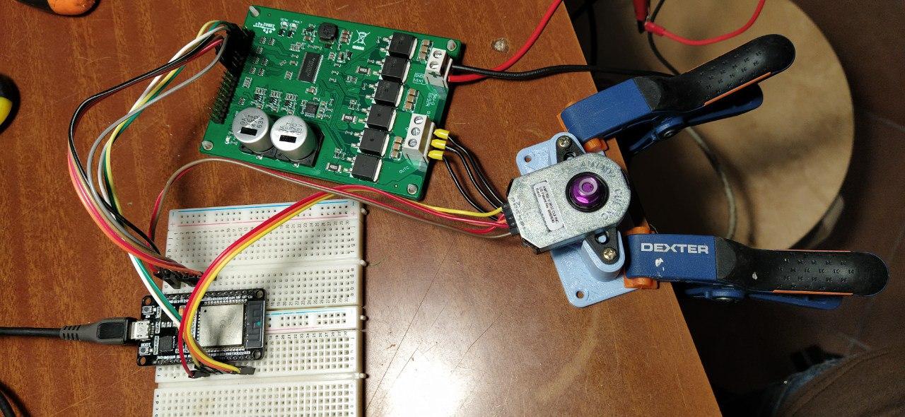
The setup is ESP32 DevKit, DRV8302, 5330 Brushless motor, AMT102-V.
It seems to me that NOT using the index pin makes things better.
My main question is: Are there suggested pins to use/avoid?
Should I turn off wifi and bluetooth?
If I understood correctly your ESP32 is restarting randomly? If so, my first guess is that your power supply is not being able to deliver enough power (this is sometimes typical when using wifi and bluetooth). How are you powering the DevKit?
I’m powering the esp32 via my Dell USB 3.1, which on the papers should give at least 1 Amp. but i didn’t measure that. But the strange thing is that when using INDEX reading, it seems the reset loop depends on the motor position…
I’ve tried different pins, but if there is a “set of pins” which work for sure, it would be nice to put it here, avoiding everyone to read all the esp32 pins behaviour.
It should be enough powering via USB, but I’ve seen different behavior powering from an external source. When you’re not using the Index reading does it work as expected? What GPIO are you using for the index?
I’d tried to establish if this is a hardware (e.g power) issue or software issue. Not sure if you are using Arduino ide or platformio (i use the latter) but for software issues you typically see a guru meditation error message in the logs + register dump then a reboot.
Summary: ESP32 + DRV8302 + AMT102-V + DX2205-2300kv BLMotor.
esp32 is the common devkit, also known as wroom-32.
AMT102 is set at 512 ppr, and powered from VIN pin (5vdc)
Since this motor becomes neatly hot, I’m powering from a lab unit, set at 12V - max 5A.
RESULT:
With these pin and settings there is a good calibration and in 10 tries no reset loop (guru meditation).
but sometimes, in position mode, after being still in a position for 3-5 seconds, it suddenly try to go somewhere at exagerate speed, asking for exagerate Current (my lab unit clamp it at 5A…) and I can only reset the board to stop it…
I’ve done a Video which reproduce the behaviour.
After calibration i set new position to 62, then to 0, then to 62 and 0 again, then there is an error on the serial, but it doesn’t seem a guru meditation, and the motor flyies away.
I’m looking to how post the video…
EDIT:
here’s the link:
Copy and paste from the terminal (I’m programming via Arduino…)
MOT: Monitor enabled!
MOT: Init pins.
MOT: PWM config.
MOT: Enable.
MOT: Align sensor.
MOT: Absolute zero align.
MOT: Searching...
MOT: Success!
MOT: Motor ready.
Motor ready.
Set the target angle using serial terminal:
Target : 62.00
Target : 0.00
Target : 62.00
Target : 0.00
ets Jun  8 2016 00:22:57

rst:0x1 (POWERON_RESET),boot:0x12 (SPI_FAST_FLASH_BOOT)
configsip: 0, SPIWP:0xee
clk_drv:0x00,q_drv:0x00,d_drv:0x00,cs0_drv:0x00,hd_drv:0x00,wp_drv:0x00
mode:DIO, clock div:1
load:0x3fff0018,len:4
load:0x3fff001c,len:1216
ho 0 tail 12 room 4
load:0x40078000,len:10864
load:0x40080400,len:6432
entry 0x400806b8
MOT: Monitor enabled!
MOT: Init pins.
MOT: PWM config.
MOT: Enable.
MOT: Align sensor.
MOT: Absolute zero align.
MOT: Success!
MOT: Motor ready.
Motor ready.
Set the target angle using serial terminal:
I’m starting to think that it could be just some PID setting problem…
now I lowered the I value to 0.1 (from 1.0) while K=20.0. Movement is precise, and it seems the motor doesn’t run away anymore…
so:
P=0.01
I=0.1
K=20.0
R=300
L=50
F=0.01 (I really don’t understand what this changes…)
So now I’m going to try to implement my own up/down acceleration ramps although I think that should be a VERY interesting addon for this library…
Do you have any suggestion on my numbers, or on the esp32 pins I used?
Thanks again, Davide.
2300KV motors do not like to run slowly! They’ll pull a lot of current. I’m using 100-200KV gimbals which have a resistance of 10ohms. I reckon your motors resistance will be about 0.5ohms - hence the high current. It’s not a problem if your power supply and board can handle it.
By the way - I’d recommend tuning in velocity mode and getting that sweet before moving on to angle mode as the angle PID relies on a well tuned velocity PID and it’s hard to do both at the same time.
L=50
F=0.01 (I really don’t understand what this changes…)
What is L? - that isn’t a config value I’m aware of? F is probably Tf - which is the amount of smoothing done on velocity. You’ve only got 512cpr which is quite low so if you ask for instantaneous speed it’ll come out like this 839, 0, 0, 0, 842, 0, 0, 0, 0, 845 as most ‘loops’ in program happen without your encoder ticking over. With this smoothing the speed will look more like 242, 220, 200, 180, 246, 220, 200, 180, 243. The PID loop finds it easier to deal with this smoothed velocity but it is adding lag so you don’t want it to high.
Those letters are for changing values on the fly. Taken from an example:
 List of commands:
    - P: velocity PID controller P gain
    - I: velocity PID controller I gain
    - D: velocity PID controller D gain
    - R: velocity PID controller voltage ramp
    - F: velocity Low pass filter time constant
    - K: angle P controller P gain
    - N: angle P controller velocity limit
    - L: system voltage limit
    - C: control loop
      - 0: voltage
      - 1: velocity
      - 2: angle
    - V: get motor variables
      - 0: currently set voltage
      - 1: current velocity
      - 2: current angle
      - 3: current target value
All your pins seem fine. GPIO 5 will output a PWM signal on boot, but this shouldn’t cause you any problems.
Your L (voltage limit) is too high. Specially for motors with a really small winding resistance you want to set this to nice limit as to not draw to much current. I set a value that I know my motor will be able to handle and not get too hot.
You can modify the acceleration ramp by changing R, it’s in termos of voltage over seconds. You can play changing this value and see the different behaviors.
Ops, my fault, I’ve confused L with N…
I’ve set L (voltage limit) to 1.0 (with 12V input) to make all the tests and N=50 which is the “angle velocity limit”.
In Velocity mode, my P and I settings seem to work ok, sudden speed changes are done as expected. the only bed thing happening is sometime, without any special reason, the motor run away, asking for exagerate current, even with the voltage limit set at 1.0
This happens with the INDEX. if I don’t use the index everything is ok…
What you are describing now might be really a software bug.
Does this happen only when you set the position to 0?
I’ll have to investigate this behavior but it might be that the index handling routine is the one which is responsible for this.
I had tested it extensively but I did not use a motor which is as fast as yours and maybe the vibrations around the 0 (where index is located) are causing it to skip count. I am sure but this might be it.
To verify this:
Could you please include motor.monitor() in your arduino loop() and show us the serial output when this happens.
What should happen is a sudden jump in motor position.
I understand your intuition. I’m trying that right now, and after some movements in which the error doesn’t happen while going back and forth to zero (I can see the first number, which I guess is the current position, slowly oscillating from -0.0xx to +0.0xx), i started it again and made a video, in which at the first movement after calibration, giving 5 as the destination, the motor suddenly run away asking more than 5 Amps from the power supply.
You can see it here, and you can hear the motor when it runs away.
So from what I can see from the video it seems like an index handling problem. But it is very hard to see on the video because it happens so fast.
Could you please dump the contents of your serial monitor to a file and post it here somehow. That would be very helpful!
You could remove motor.monitor(); and put something like this in the loop.