It might be an error on my board, but I always have to define both drivers, even if I use only one output.
I noticed it, because I had two motors connected and the undefined motor started squealing.
I’m using the _NC as in the Hall sensor examples of the SimpleFOC documentation. There are some changes with the DengFOC library.
shunts are 0.01Ohm, amps are INA181A1=20x gain
//MKS Dual FOC Plus
InlineCurrentSense current_sense = InlineCurrentSense(0.01f, 20.0f, 39, 36, _NC);
Yeah, I had both defined at first but ignored the other one. I don’t have a motor connected but I could try with the other driver and compare.
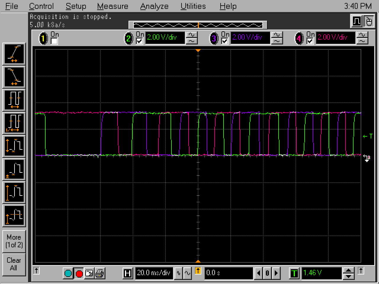
Added some filtering, getting very nice hall signals with no noise:
But still the same as always. Here is a video with the Target voltage set to T1 and the motors stalls at the low speeds:
And another video of the stuttering at higher speeds:
If it worked well in voltage mode, I assume hall signals were OK.
Is your main loop running fast enough?
Loop is running at 65kHz, a lot better than the Arduino (1kHz) and the Blue Pill (22kHz)!
edit: loop is not running at 65kHz, driver section was not powered, correct measurement is about 6.5kHz
Hey, if the loop is running at 65kHz, what’s the PWM frequency?
You may in fact find it works better with a small delay. At this frequency, and with Hall Sensors, velocity calculations will be very inaccurate, and presumably multiple updates of the PWM levels within the same PWM cycle won’t be contributing much…
In general, since the PWM frequency imposes an upper limit on how often you can update the phase currents, it does not make any sense for the FOC loop to run faster than the PWM frequency. Probably 1/2 the PWM frequency is a good upper bound for the loop speed.
Hi runger,
I measured the frequency wrong with no power to the drivers, it’s closer to 6.5kHz.
I did try adding a delay so the loop ran at 500Hz and tried changing the PWM from 4kHz, 8kHz, 16kHz, 20kHz and 26kHz.
One of the motors runs a bit smoother and for longer.
Also, thanks to everyone for your time and input so far ![]()
6.5kHz is not so much ?
Are you using SVPWM or SinePWM ? Is it running smoother with SinePWM ?
Hi,
5hHz SVPWM
5.5kHz SPWM
5.6kHz Trapezoid_120 (HORRIBLE cogging)
9.5kHz No modulation selected.
edit: this is with two motors. getting 24kHz with only one motor enabled and no modulation set
Open loop is so smooth… like my brain feels now…
Get one motor running smooth with hall sensors first.
Yeah, that’s the exact issue I’m having all along.
I’m going through the setup tests again for the other motor now just to check it’s not one of the drivers or something.
edit: halls checked, phases checked, open loop velocity and position check. Closed loop… same problems.
I had a hard time soldering the ESP32 female headers to the controller. After inspection with a magnifier I found four cold solder spots ![]()
I also couldn’t find any pullup resistors for the i2c/hall connectors.
Using sensor.pullup = Pullup::USE_INTERN; didn’t help either.
I guess, they skipped these resistors for a more multi-purpose interface.
I’ll add an adapterboard with 5V level-shifter and pullups for the halls. On the hoverboard the halls were powered by 5V and the pins of the MCU were 5V tolerant.
Can’t say for the Espressif chip, whether there are 5V tolerant pins?
Hey o_lampe,
Are you using the MKS Simple FOC Dual or the Plus variant?
The hall sensors should run fine on 3.3V (many work from 3 to 5V). I did end up adding 3k pullups as the internal ones are very weak and I wanted to make sure the signals were proper. Also added LC filter to get rid of the switching noise (pretty sure the hoverboards also have this implemented).
I did recheck my solder joints, as you say, the headers are surprisingly harder to solder than they look! But flux is your best friend here ![]()
I do notice the ESP32 is very loose in the headers and I think I’ll add a rubber band to make sure it’s not causing problems too.
Some STM32’s have 5V tolerant pins, but not the ESP32!
I have the Plus variant, since the other doesn’t make sense for hoverboard motors.
The other version comes with 4.7k pullup resistors BTW.
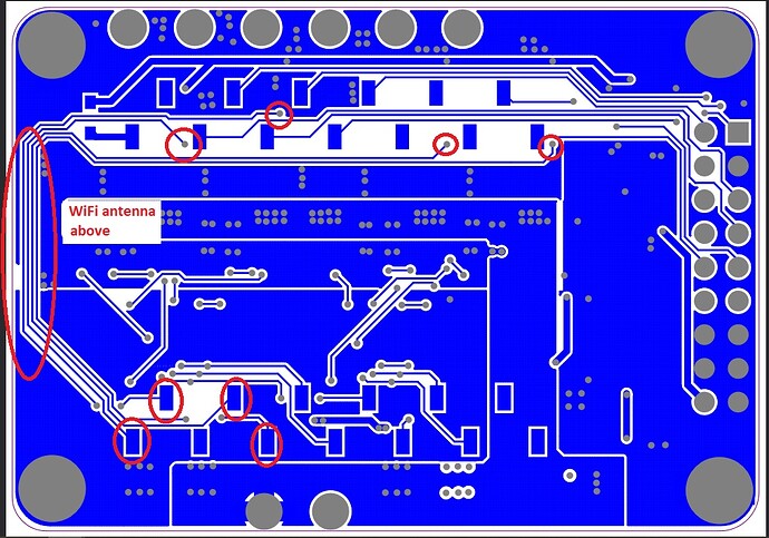
Did you see how they routed the current sensor OpAmp signals to the ESP32? They go all around the PCB and right below the WiFi antenna…
Yeah, there are many questions about the designs itself. but then the DC bus does kind of cut the board in two xD
I have no plans for wifi and worse comes to the worse some foil or even a shielded enclosure. Shouldn’t interfere too much both ways I’d hope.
Do let me know how your setup is going, I’m looking forward to your results with the same board and hoverboard motor!
I continued reading the documentation and decided to measure the motors KV, resistance and inductance to see if it helped but… same issue.
Measured:
0.75Ohm
38KV
1084uH 350khz // 1190uH 50khz
Changed from 12V to 24V,
I don’t know… I’m stumped as to what to check at this point…
I also use hoverboard motors, I need to measure the resistance and inductance also.
But I can tell you the KV is wrong. It should be 15-16.
I took a big step backwards and started testing the MKS controller with a small gimbal motor.
I want to find a working inlineCurrentSense setup that works without jumping from the workbench ![]()
@Candas1
Yeah, I was expecting a lot lower value too… hold on…
Yup, my bad, the online calculator uses the number of poles instead of pole pairs. The result is 19KV, still seems a bit high. Gonna try this value…
Works a tiny bit better hahahah ![]()
@o_lampe
I don’t think I have any other BLDC with hall sensors, maybe some 500W Dunkermotoren ones but they are again big motors. I have some quad-copter motors somewhere…
For inductance I was using something like 0.000369, it was working well. But I haven’t measured it.


