Hi all, I got another board and changed the pwm frequency down to 1kHz. I also tried 2kHz but that didn’t make much difference. I connected a “10C” DIN-rail circuit breaker to the battery just in case. I reduced the motor voltage limit to 0.75V. Current limit is 2A. I use current sensing and voltage torque control. Velocity control for the motor in closed loop. While running I read a number from the serial line and set the velocity target to that. If I set the velocity to 30 it runs reasonably well and fast and has good torque while it also emits some high pitched sound. If I set the speed to below 21 it still runs but looks like it’s struggling, doesn’t sound right (hard to describe) even though the mosfets are only slightly warm and rpm looks as expected. I tried setting the phase resistance to 0.039 Ohm but the motor doesn’t move to calibrate with that. Good news is that nothing has blown (yet) and also the 10A fuse hasn’t tripped yet. We also have an oDrive that runs the same motor beautifully but unfortunately that is closed code. I guess I have to read up and experiment more with the parameters which probably doesn’t belong to this particular thread but just wanted to give an update here.
Thank you. Glad it’s working out for you.
You may benefit from creating another thread just for your tuning. These integrated drivers are a little slow and will need separate tuning.
ODrive is actually open source. The PCB is also open source. You are free to modify and load on your own board. There is an ODrive Arduino library inside, too. I’ve never tried to do anything with it, so you are on your own.
https://github.com/odriverobotics/ODrive
These are the schematics for version 3.5
I believe the newer schematics are closed source but 3.5 seem to be good enough.
The schematics are very educational for people trying to develop their own boards. Some of the decisions made by Oskar are not exactly industry grade but work for a hobby board. He may have fixed them in the later releases which are closed, so no comment there.
Cheers,
Valentine
I believe the Odrive use FETs in parallel to decrease on_resistanse. It’s all about the attainable switching frequency in the end.
That’s one of the issues I referred to. There are beautiful and really nice low resistance high power mosfets, there is no need to parallel mosfets. However this is neither the place nor time to criticize Oscar’s work. I’m sure he knew what he was doing at the time.
Valentine
Naturally gate charge also plays in.
Not following here. Double mosfets double the gate charge, so?
NTMFS4935N is 30V/93A rated, 22nC gate charge, 3.7mO resistance, that’s what Oskar is using on ODrive.
Double the above, 30V/186A, 44nC, 1.85mO
IPT015N10N5 is 100v/300A rated, 200nC gate charge, 1.5mO resistance
I take IPT015N10N5 any time to double NTMFS4935N in parallel. And the driver used on ODrive is fully capable of driving the IPT015N10N5 mosfet anyway.
Let alone, doubling mosfets is exposing you to some questionable issues when they don’t quite turn on the same time and at high power you get them smoke and burst.
As long as it works and makes people happy though, I guess it’s fine.
Cheers,
Valentine
PS that picture I posted above, that’s with IPT015N10N5 mosfets. It’s an absolute monster of a driver.
@Antun_Skuric Do not know if someone will read this message… But. BTN8982 is a good IC. And it is capable of doing pretty good FOC on 20kHz. Only thing you need - to use 0.5 PWM as neutrall on all thre phases instead of 0 as the neutral. BTN8982 has pretty big ‘deadzone’ on small duty cycles. So when you need to set f.e 0.05 or even 0.1 it can happen that it will remain closed - so we loose precision. But when the neutral is 0.5 and we need to set 0.05 relative to it - it will be 0.55 or 0.45 of duty cycle. And brige will be open with guarantee. It will work with either precision you need when using 0.5 of duty cycle as the zero. I utilise it on my custom board with great success.
Hey @olukelo,
Happy to hear that you have great results with it. I’d be happy to see some videos and some code maybe?
Regarding the half of the duty cycle, we do use center aligned pwm the behavior you’ve explained is already a default behavior of the simplefoc. It is true that by center aligning the pwm, you can locally reduce the error base on the long duty cycle. However it will still be there. You might be able to model it and compensate for it.
We in the simplefoc are interested in the solutions mainly as generic as possible and adding such a hardware related option is the library is not in our focused for the moment. ![]()
However were always open for collaboration.
I’d just like to make a disclaimer here, BTNs are going to work and even on the higher frequencies of the PWM, but they will need more work to be an efficient solution.
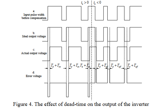
Standard simplefoc library will do the job, but without proper compensation for the losses of the long dead time they will start heating a lot for higher pwm frequencies > 15khz.
However their huge current capacity and simplicity of integration is so tempting that it’s definitely worth of digging deeper into and I’m sure some of you guys will be able to have some great results for your projects.
@Antun_Skuric
What do you mean by this? What kind of compensation, what parameters should be optimized? I was thinking of getting a couple of BTS7960 dual IC modules (1 and a half should drive one BLDC) since that’s what I can get my hands on quickly, and they seem similar to BTNs.
They are the early version of the BTN8982, very old (1990s), slow, and even worse heat dissipation. It may work, but don’t be surprised if they pop from overheating.
What I meant is that due to the long rise times of the mosfets the effective duty cycle set to the motor vs the duty cycle that you calculated will be different and the this will prevent the smooth operation. Now, you could potentially find the relationship in between these two values and use it to correct the duty cycle value you are setting to account for this difference. This might make the operation a bit smoother.
It is hard to say how much of the improvement could you get really, but it seems like an interesting thing to try ![]()
Thank you @Antun_Skuric
If I got it right, this paper describes the issue and the solution. Radware Bot Manager Captcha
Pls let me know if I’m wrong and I’ll remove the link if that’s the case to not bring confusion in.
There is a open source project building a brushless motor driver with high currents here: open-motor-driver-initiative/hardware at master · open-dynamic-robot-initiative/open-motor-driver-initiative · GitHub
They use the DRV8353 chip as driver and then 3 x CSD88599Q5DC for the power stage.
The project has a forum (https://odri.discourse.group/) in case you want to reach out to them.
high currents
I’ve designed couple boards with that dual mosfet, its not high current, but medium to small, and voltage relatively low. Plus the heat dissipation is rather poor, coupled with extra small footprint requiring thick copper layers with heatsinks, making the board expensive for open source projects.
The mosfet itself is expensive, three of those are about $15 retail.
Infineon’s IAUC line is less than a dollar with somewhat comparable performance. And the Chinese knock-offs are about a quarter a piece.
That CSD line of mosfets is however really good for fast sensorless applications with forced air cooling and where space is very important. The drone community really likes those.
Cheers,
Valentine

