Hi All, im following along with the simpleFOC mini tutorial here;
my hardware setup , motor, encoder is identical to the tutorial (GBM4108H-120T
and AMT103) except that im using a Teensy 4.
Im able to get most of the examples working except the closed loop position control. I used the code in the tutorial here:
im getting a buzzing / twitching behavior on the motor. I tried tuning the PID and while that calmed the buzzing down I am unable to change the angle.
To rule out any hardware issues, I did verify open loop position and voltage control works, I also verified the encoder works and is outputting correct values.
Are there any nuances with the teensy and modifications I need to make to the example code. Most of the examples use the arduino.
I do have a ESP32 that I coud try but ideally id like to get simpleFOC to work with the teensy.
Still struggling with getting the Teensy to work with closed loop position control. Is the Teensy not the recomended MCU to used with this Library?
My issue is likely with the encoder . Pin assignments seem fine as all pins except 13 are HW interrupt pins. the AMT103 is a very popular encoder for use with SimpleFOC. Im using the recommended settings in the example code. Im at a loss.
Greetings Antun, first, I am so thankful to you for this amazing library.
I have posted further details on the discord channel:
To summerize.
Yes, I have tried the open loop velocity and position code and that works fine. I have also verified my encoder is reading correctly by rotating the motor manually 360 degrees and checking it. That also seems to be perfectly accurate. I have also used the pole-pair utilitiy and landed on 11 for my motor. With all this, I was able to verify step 1 and 2 work perfectly.
I do not have a electronics power supply yet. Regardless, I took care to supply clean 19v using a laptop power supply, I am using the 3v3 output from the teensy to power the Mini board and the 5v output to power the encoder. I also tried to use a 4S lipo but that resulted in similar behavior. I do need to verify that these voltages are what is to be expected using a volt meter. I will do that. It may be there is noise due to powering the sensor and board from the teensy, perhaps i need to isolate power completely?
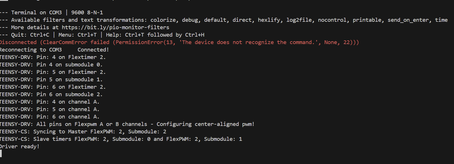
Finally, when I run the code linked above I do not get any Hardware warnings or errors in the debug. As you can see in the video, the motor tries to “home”, and then freaks out.
I purchased the SimpleFOC mini boards from Ali Express, I purchased several as I know the quality is questionable. Seem all boards I have show the same behavior. Here is a short video of the cogging. https://youtube.com/shorts/9rH5sI6M7tY.
I greatly appreciate your input, and when resolved, I will make a video to perhaps help others who may come across similar problems.
The line liba_archive=True is necessary, if you don’t set it the code will try to use the Arduino default functions, which are not always implemented for all architectures. For teensy they are though, but the PWM frequency is at 1kHz, hence the high-pitched noise. So the fact that you dont hear the noise any more is a good sign. And especially since you see the TEESNY-DRV outputs in the serial, this means that the correct code is being used.
So yeah, its a bit strange. It should work, if the first two steps did go well. If the open-loop works then the driver is fine, and the power-supply should be fine as well.
If the sensor test works, then the sensor is fine as well, especially since it’s the amt102 encoder, they are very reliable.
Failed to notice movement indicates two things:
if the motor moved, then it is the sensor issue, it did not read any values
if the motor did not move then, there is an issue with the driver (but that seems not to be the case)
Debugging the sensor issues
So then can you verify that the sensor is well fixed and that the inner shaft is not slipping.
Can you also verify that for one full rotation of the sensor you have exactly 2pi ~ 6.28 rad read?
Last thing that you can try is to run your example in the velocity_openloop mode (or angle_openloop). The init will not pass but that is not a big deal, you just need to enable the motor (motor.enable()) after the initFOC call. And then in the main loop you can print the motor position encoder.getAngle() after the loopFOC and move call.
You should be able to see coherent sensor readings even though the motor is controlled in the open-loop. If you don’t see any sign of movements in the sensor readings that probably means the sensor is somehow not initialised well.
Note: P and I are initially 0 and use the command input to tune P. I have also set I = 1 and then tried to tune P. Setting LPF_velocity.Tf = 0.1; smooths out the ocolations
So clearly, something specific inside the closed loop mode is causing issues. I wonder if there are any additional build flags that would be useful?
So you do no longer have the issue Failed to notice movement. That is great.
Did you try using voltage torque control?
Does it behave well?
It does not use any PIDs so this at least removes the gain tuning factor from the equation.
ah yes I did try voltage torque control using
motor.torque_controller = TorqueControlType::foc_current;
motor.torque_controller = TorqueControlType::voltage; (since its a Mini)
that works. Its when I go to the velocity control using PID i get shaking like in the video ( ```
motor.controller = MotionControlType::velocity;
I did not use ```
motor.PID_velocity.output_ramp = 1000;
``` but i'll try that.

I'll also try setting motor.voltage_limit = 1.

Perhaps the PID controller is asking too much from the motor causing spikes?
i found this thread that may be related to my issue. Seems I am not the only one that has trouble with closed loop vibrations. I will try the suggestions here;/ Gimbal motor overheating - #6 by Valentine
Ok that’s great. So it’s either the PID tuning or the velocity measurement that’s problematic.
As teensy boards are very fast the velocity calculation can be pretty noisy. You can down sample the velocity calculation using the encoder.min_elapsed_time value.it determines what is the minimal elapsed time after which the sensor will calculate the new velocity value. By default is 100us if I’m not mistaking. You can set it to a few milliseconds.
encoder.min_elapsed_time=0.002; //2ms
This will make your velocity calculation much better. Then you can tune your PIDs afterwards.
the teensy is very powerful and small formfactor, so I am not giving up yet. It is indeed strange that the voltage loop would work yet the velocity loop does not. I will plot the velocity and see if it is noisy.
Mechanically ,its impossible for the encoder to slip. I created a rigid shaft that mates directly with the encoder without the friction fit that the AMT103 comes with. As stated earlier, I verified that the encoder is working by having the motor rotate 360 and printing out the encoder values and the encoder also read exactly 360.
I could try 6PWM on the teensy but im guessing if 3PWM isnt working right than 6PWM wouldnt be much better.
Yeah, is the voltage loop works, that means that the encoder and driver are working well. There is no point in changing the MCU or the sensor or the driver, everything works.
There are two things that are different when you change from the voltage to the velocity loop
the loop is closed over the velocity calculation which might be noisy
the PID parameters can be bad making for an unstable behavior.
There are no other real reasons why would it not work.
I imagine that the vibration behavior does not happen if using only a small P value right?
If it does, this probably means that the velocity calculations is noisy. Then increase the encoder elapsed time parameter even more, but I guess that you’ve tried this right?
If the motor is stable for small P values and then becomes unstable for higher values, then it might be an issue of choosing the appropriate PID values.
What you can also tey is to down sample the motion control loop using the motor.motion_downsample parameter. Try setting it to 5-10 or so. This will run the motor move each 5-10 loops, making the time between the calls a bit longer and possibly making the PID tuning a bit easier.
Hello Antun. Quick update. So indeed it was a PID tuning issue. I was able to get stable PID velocity control but only for higher speeds. At lower speeds the rotation is unstable. I am still new to all of this but apparently low speed jitters/cogging is a common problem with non-obvious solutions. What comes to mind is to turn off PID below a threshold…etc. However with this specific encoder/bldc motor combo, im surprised im unable to get good behavior at lower speeds because This is the exact same motor and encoder you used in your self balancing robot and surely in your robot the wheel is very smooth across all ranges of wheel speeds. The only thing different in my setup is that im using a mini which does not have current sensing. . Ive tuned the PID the best I could, I’ll still need to exports some plots and post on here but if you have any initial thoughts let me know. Here is the latest code. For target speeds < 20 I start to get ocelations. FOCTests/src/main.cpp at master · anupamdas2012/FOCTests · GitHub
So 20rad per second is not really low speed, you should be able to get good velocity control loop all the way down to 1rad per second even less.
Id say it’s still the issue of the velocity measurement, please try to plot it somehow
If that’s the issue you should be able to get better control if you tey using higher encoder.min_elapsed_time (try setting up to 10-20ms) and motor.motion_downsample (try setting 10 up to 150)
For the PID tuning, start with only P. If the velocity is not noisy, you should easily have vers table behavior (not very good following of the target velocity) but very stable. Then add some I slowly.
Greetings Antun,
So, turns out I was using the 5v pin on my Teensy to power the encoder. I switch that to using the 3v3 pin and practically all of the noise went away and now close loop velocity is silky smooth across all RPM range. The PID tuning parameters from your examples and suggestions now are starting to make sense and show the behavior i would expect where as before there was just noise in the system. I know many of your examples use regulated logic voltage from the MCU, but in a “production” environment is it recommended to use a separate regulated power source for logic instead of using logic power from the MCU?
This was a gigantic hurdle, thanks for all your help.
On to Closed loop angle control!