Hey guys,
New Lurker here, could anyone give me an example code?
the hardware is a Nema 17,Arduino Due,Omron clone encoder and L298N motor driver.
I want to be able to use analog inputs on the Due to control DIR/PWM.
is this possible?
Hey guys,
New Lurker here, could anyone give me an example code?
the hardware is a Nema 17,Arduino Due,Omron clone encoder and L298N motor driver.
I want to be able to use analog inputs on the Due to control DIR/PWM.
is this possible?
Hello and welcome to the forum.
Yes it is possible. You need to use free two pins, one 0/1 for forward/reverse and another for reading PWM and converting to a number between 0 and 1 and then scaling for the speed you need.
You need to write your code on top of the main loop.
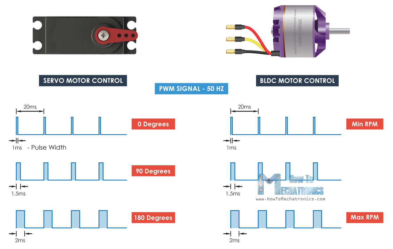
Question: What is the PWM you intend to feed? Most DIY-ers say PWM, however, inconceivable, this is not what they think it is. The PWM for ESC that the DIY-ers talk about is this:
while the MCU PWM is in fact just a duty signal between 0 and 100% at any arbitrary frequency.
Please be very specific in your requirements and use cases and describe in more details what you need so others can help you.
Cheers,
Valentine
If by PWM you mean the style that radio control servos and ESCs use (approximately 1000 to 2000 microsecond pulse), my code looks like this:
volatile uint16_t servoPulse = 1500; // Can be changed at any time by interrupt handler

void ServoPulseUpdate() {
  static uint32_t startTime = 0;
  uint32_t curTime = micros();
  if (digitalRead(SERVO_PWM_PIN)) // Pin transitioned from low to high
    startTime = curTime; // Start counting pulse time
  else // Pin transitioned from high to low
    servoPulse = (uint16_t)(curTime - startTime);
}

setup() {
  pinMode(SERVO_PWM_PIN, INPUT);
  attachInterrupt(digitalPinToInterrupt(SERVO_PWM_PIN), ServoPulseUpdate, CHANGE);
}Thanks! However, based on the question, I believe this would be too complicated for @simracer.
Could you please explain how to include this in the main loop? We will need to check for the PWM between 1000 and 2000 us and scale between 0.00 and 1.00 then multiply the max speed (I assume min speed would be 0.00) then feed it to the FOC velocity.
Also we need to check another pin for 1/0 to specify direction (the velocity sign) so we should multiple the velocity either by 1 or -1 before we feed to the FOC control loop.
In a way we made a velocity servo out of FOC closed loop. He will have a problem with switching the direction because without speed rampup and rampdown S-curves it may tear the motor but at slow speeds it should be OK (may be not?). May be he can manually control the ramps then?
Another approach would be we split the 1000us to 2000 us into two 500 us and then assign the sign based on which side of the 1500 us we are. This way we avoid the extra pin and simplify the algo but lower the resolution. May be at most 10 steps on each 50 us would be sufficient for a hobby project. THis way he will be forced to go through the range and in a way force the motor to rampdown before rampup in opposite direction.
Did I get this right?
Cheers,
Valentine
void setup() {
  Serial.begin(9600);
  attachInterrupt(0, isr, RISING); // D2
}
volatile int pulse, period;
volatile bool state = false;
volatile uint32_t tmr;
uint32_t showTmr;
void isr() {
  if (!state) {
    state = true;
    attachInterrupt(0, isr, FALLING);
    period = micros() - tmr;
    tmr = micros();
  } else {
    state = false;
    attachInterrupt(0, isr, RISING);
    pulse = micros() - tmr;
  }
}
void loop() {
  if (millis() - showTmr >= 500) {

    Serial.println(100.0 * pulse / period);
    showTmr = millis();
  }
}
I tried it with arduino nano. Readings are unstable
That’s expected. Using this for any real world application requires kalman filtering and/or at least some basic averaging. Then you need to bin it into buckets and then handle the edge cases separately with a hysteresis logic.
Yeah, the pulse time from standard RC equipment tends to jitter around by a few microseconds. For RC servos, the usual solution is a simple threshold value called deadband. Don’t update the target position unless the new value calculated from the pulse time is significantly different from the measured shaft position.
For velocity control like standard ESCs, there’s no need to filter it. The momentum of the motor smooths out the jitter of the target speed.
Hehehe, right. It won’t matter as long as you aren’t aiming for the Cassini Gap.
Wow, Thanks for the response everyone.
it is going to be for a force feedback brake pedal with a stepper motor on a ball screw.
the logic will be controlled by another MCU that I can program through XOD.
I will be outputting a 0-100% PWM signal the default arduino 490.2hz and a digital 0/1 for dir.
essentially I want to treat the Simplefoc controller like a half bridge motor driver controlling a DC brushed motor. if that makes sense?
If this is a real-time haptic feedback system, you may want to reconsider PWM and a second switch for direction. In that case you will make your life a lot easier and your system a lot more resilient if you use the 3.3V ADC and read in only one analog signal centered around 1.15V. At 1024 resolution you will get at least 100 steps resolution each direction and instantaneous real-time feedback and avoid any FOC delays in reading the PWM and direction then overlaying an algorithm on top.
Get a good controlling MCU that has at least one DAC. Use the controlling MCU to write a DAC signal to the analog output pin and connect that pin and ground to the SimpleFOC to form a simple differential pair, use a shielded twisted pair two-stranded cable and read the analog signal on one of the analog pins of the SimpleFOC MCU as part of the main control lop. Forget about PWM, algorithms, protocols, etc. Keep it really simple. Then do a simple rounding by removing the last two bits (if 10 bit, get it down to 8 bit) to make sure you get rid of the noise and you get 128 steps in each direction. That’s way more than you’ll ever need for a haptic feedback pedal.
For example, ESP32 has two 8-bit DAC channels. STM32F446xC/E have two 12-bit DACs. Arduino DUE has two DACs.
Or, if you are using the classical Arduino such as UNO, I’m a huge fan of hardware solutions. Output normal 32kHz PWM and use a simple low-pass RC filter to convert to analog then use the ADC trick. You need however be careful because of the transient response time of the filter. Also the UNO works on 5V so you may get a little problem there making sure you match the voltages. Or you could go the king’s road and use a DAC chip? May be an overkill.
Cheers,
Valentine
very good points, but an analog signal over a pwm?
I have Esp32s, Stm3xfxxx’s, arduino due’s and i have some Pwm to Dac converters.
so then basically i would only need code that would run of a potentiometer basically lol
I just need to be able to control torque/ force.
")
Correct. Keep it simple.
So you’re wanting to read a 490.2Hz PWM signal? At a frequency that low, I’d just use an interrupt to measure the high and low time period rather than bothering with conversion to and from analog. Something like this (untested):
// Can be changed at any time by interrupt handler
// Range -1.0 to +1.0, sign depending on state of dir pin
volatile float pwmDuty = 0;

void PWMInputInterrupt() {
  static uint32_t startTime = 0, lowTime = 0;
  uint32_t curTime = micros();
  if (digitalRead(PWM_INPUT_PIN)) // Pin transitioned from low to high
    lowTime = curTime - startTime;
  else { // Pin transitioned from high to low
    uint32_t highTime = curTime - startTime;
    pwmDuty = (float)highTime / (lowTime + highTime);
    if (digitalRead(DIR_PIN))
      pwmDuty = -pwmDuty;
  }
  startTime = curTime;
}

setup() {
  pinMode(DIR_PIN, INPUT);
  pinMode(PWM_INPUT_PIN, INPUT);
  attachInterrupt(digitalPinToInterrupt(PWM_INPUT_PIN), PWMInputInterrupt, CHANGE);
}
EDIT: Added check for dir pin as well. I chose dir=0 forward, dir=1 reverse, but of course you can invert that if you want.
Also, this code assumes that the PWM cycle begins with the low period and ends with the high period. If there can be large instantaneous changes of duty, then you need to know for sure that this is correct, else you’ll get the low period from one cycle and high period from the next cycle, and the calculated duty will be wrong.
Personally, I like the idea of a “PWMDirListener”, as it would open a door to compatibility with a huge amount of standard RC gear. Something like this would be a requirement for a SimpleFOC based RC-ESC if it were aiming to be compatible with standard receivers, etc…
However, I think the code will have to be a little more complex, to take into account that there can be different pulse-widths, minimum and maximum values.