Hello,
Can we simply do a sensorless with SimpleFoc ?
Hello, yes it’s possible.
I think you are looking for this:
Hello,
I meant a true sensorless with closed loop velocity
Is it possible with simplefoc ?
Hello @Marc_O
Interesting question. Would you mind elaborating on what true sensorless closed loop is?
By definition a closed loop requires signal feedback. I mean, System Controls textbook definition, else this is not a closed loop control. You need at least one real-time signal telemetry feedback received and processed at least at the control frequency to achieve a closed loop. Signal estimation (prediction) in case of well-behaved systems is also acceptable.
Please elaborate your question with an example.
Cheers,
Valentine
Edit: Reference to clarify my comment
It is not possible with SimpleFOC. To do sensorless velocity control BEMF readings would be enough to do so. To do sensorless position control there are a few very complicated techniques to do so, HFI (high frequency injection) for example.
Many thanks for your answers, and reaction.
In fact as you know, there is several technical ways, one is described by David for exemple (HFI), but they also exist the PLL or/and backemf sliding mode observer or others observers to get back emf and so on.
There is ODRIVE, VESC for exemple that uses a mode here above.
My question just was to know if it was possible to implement this in SimpleFoc easly, because it is interesting to get this for some application ?
You are confusing “sensorless” with “no external sensor” and “closed-loop”. Neither BEMF nor HFI are sensorless. These are closed-loop, sensored algorithms. However instead of external sensors they using the EMF from the motor coils as a signal feedback sensor mechanism. I think you are mistaking the concept of “sensorless” as “no magnetic or optical sensors feeding the MCU algorithm via a dedicated cable”. Also, the open loop by its very definition is sensorless, as in absolutely no feedback, not even BEMF or HFI.
Especially BEMF could be used to commutate the motor without an external algorithm or MCU, you just need a few capacitors and resistors, and also this is not FOC anymore, more like a brushed DC motor, and usually you see this in ceiling fans and computer cooling fans. Which is still a closed-loop hardware algorithm, hard-wired to run at a per-determined angular sped.
I am not nitpicking. This is the basics of Control Theory.
I saw somewhere on this board a PCB that used BEMF Op-Amps, and I am sure code could be written to use the Op-Amp BEMF signal to commutate the motor. If I search a bit I will find it.
Cheers,
Valentine
Edit: Found the BEMF capable board.
In general “sensorless” is considered the lack of using an external sensor to drive a brushless motor, so only having to connect the motor to the driver. Neither BEMF or something like HFI need an external sensor. The fact that it is, in strict sense, a “sensor” to use a close loop controller is not what we (and the community in general) mean.
Agree. However the thread mentioned “I meant a true sensorless” which means no signal feedback at all. I am probably reading too much into this and should shut up at that point. I don’t want to be that one guy who always tries to correct everyone.
Are you familiar with Flux Observer or other technics?
In my opinion, it is possible and valuable to implement a sensorless plan.
But before asking other guys to make it, why don’t you build it yourself? I am sure that it is a good idea and we all will be grateful for your contributions.
If you are interested in Sensorless Control, some papers will be helpful:
I feel Marc_O rise a right question, I’ve the same substantial need. I don’t care definitions (sensorless or not sensorless ![]() many manufacturer says “sensorless” when using BEMF).
many manufacturer says “sensorless” when using BEMF).
I don’t understand why BEMF is not a part of FOC thechnique as Valentine said, so I have to read more a lot of documentation.
Thnx a lot to all.
Hey @Paolo and all,
I would love to implement both sensorless FOC and BEMF approaches into the simplefoc library.
It is on my agenda, but at the moment I am not working on it.
If there are people who are interested in contributing I would love to collaborate over this.
Here are few very informative sensorless FOC links:
By the way, “Sensorless FOC” in control theory stands for FOC control without using position sensor, not excluding current sensing. Therefore “Sensorless FOC” is a closed loop control approach. ![]()
A bit counterintuitive ![]()
Hi,
For me, the Sensorless FOC with current feedback only, is an Sensorless with closed loop…
With the current sensors being so cheap, using a bunch of resistors and capacitors to proxy the phase current and then still needing the op-amps to amplify the current to feed into the MCU, then use an algorithm to estimate the phase current, I really don’t understand why so many people look at this as some kind of “holy grail” of motor control. It’s a really old, poor and cheap way to control a motor, harking back from the days of my grandpas when people didn’t really have FOC and used a simple “zero cross” commutation to control the motor speed. Whoever needs “sensorless FOC” probably only needs a really simple and cheap fan speed controller, not a modern control board with a FOC algorithm.
https://www.digikey.com/en/products/detail/allegro-microsystems/AMT49406GLPTR/10498761
Adding this to the library is certainly a very interesting and academically worthy exercise, however, I see very little practical applications, furthermore coupled with the fact that there are no commercial boards implementing the phase sensing using “sensorless approach”, that is, the resistor/capacitor schematics for sensing the phase current from the coils. They all use either shunt resistors or hall-current sensors. I looked into adding “sensorless” sensing (an oxymoron) and it was so messy and complicated that I gave up. Perhaps someone else could design a “sensorless” phase sensing board, for testing, it would be an interesting and intellectually challenging project in PCB routing.
For those interested in doing it, here is the “sensorless” schematics. As you can see, plenty of “sensing” going on, not quite simple and “sensorless”.

I think there is a bit of confusion here…
one question is one of definitions. The English language is unluckily (or luckily?) imprecise, and naming prerogatives lead to logically contradictory situations.
But since no one here is to blame for it, and we also don’t benefit from introducing new nomenclature, lets just accept that sensorless control of a BLDC means not using a position sensor, and closed loop sensorless control is possible under this definition by using other sensors that sense current/voltage.
In terms of sensorless control, there is the old and true BEMF based commutation, which can be interesting for some use cases, but isn’t FOC control.
But there are also modern methods, based on some pretty cool and advanced concepts around injecting high frequency patterns on the phases, and measuring their deformation on the other phases, in order to recover information about the rotor position.
Such methods then in theory do allow FOC control.
At the moment we’re working on getting current sensing stable and useable in more situations. That will be a foundation from which to build these more advanced ideas on.
For back EMF I think there is a good case to be made, many use cases would benefit from this over plain open-loop.
I read a paper way back where you can use this technique for absolute angle control, let me see if I can find it. Pretty ingenious but computationally intensive. Let me check.
Found it. This is one of the original papers, back in the days when microcontrollers were not fast enough. Very interesting read. They used to call this “self-sensing” before they adopted a more-widely accepted “sensorless” lingo.
The technique functions in a manner similar to a resolver and resolver-to-digital converter (RTDC) sensing system, whereby in the proposed technique the motor acts as the electromagnetic resolver and the power converter applies carrier-frequency voltages to the stator which produce high-frequency currents that vary with position. The sensed currents are then processed with a heterodyning technique that produces a signal that is approximately proportional to the difference between the actual rotor position and an estimated rotor position. This position error signal and a torque estimate are then used as inputs to a Luenberger style observer to produce parameter insensitive, zero lag, position and velocity estimates.
The heterodyning technique is an analog signal processing device. Absolutely fascinating. They used an analog post-processing device to obtain real-time rotor position. In other words, a fully analog setup with an oscilloscope. The entire math was modeled as discrete analog components. Hardcore.
Hi
Just stomped across this here when reading up on the Teensy 4.
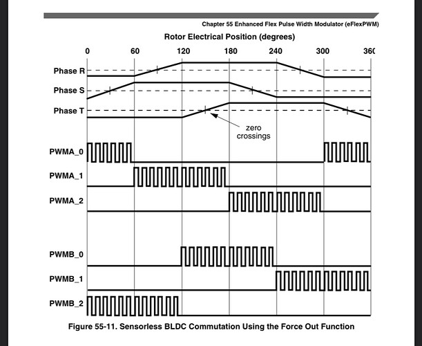
Figure 55-11 shows a popular application that can benefit from this feature. On a brushless DC motor it is desirable on many cases to spin the motor without need of hall- effect sensor feedback. Instead, the back EMF of the motor phases is monitored and this information is used to schedule the next commutation event. The top waveforms of Figure 55-11 are a simplistic representation of these back EMF signals. Timer compare events (represented by the long vertical lines in the diagram) are scheduled based on the zero crossings of the back-EMF waveforms. The PWM module is configured via software ahead of time with the next state of the PWM pins in anticipation of the compare event. When it happens, the output compare of the timer drives the FORCE_OUT signal which immediately changes the state of the PWM pins to the next commutation state with no software latency.
It’s been almost a year since last post in this thread…
Are there any news about implementing in SimpleFoc back-emf readings to control bldc motors without an external sensor? To achieve closed loop speed control? Using maybe that DRV8302 board?
Thanks!
Yeah this would be super useful for me, although I am willing to pay for a sensor if it gives smoother motion.
Let’s face it, there are already cheap sensorless drivers, and the additional benefits of an FOC driver are marginal, except for acoustic noise. There are already sensorless FOC drivers on the market, the MCF8316 for instance, might have that name wrong, from texas instruments, however it has a number of serious issues that would be overcome with an open source solution. It’s about 9 bucks CAD but suppose $13 for the actual board with it on there. It only does velocity control mode, and it doesn’t work with a lot of motors. It doesn’t work with gimbal motors, they made some poor assumptions and it gets confused.
Guys, I see a lot of desire to do a lot of things with SimpleFOC, and I think we should pick something and pass the hat and actually pay someone to do something. I’m willing to chip in. As Rimbaldo said, a year can go by with no progress, and I don’t see that changing any time soon. The reality is that a lot of open source work actually gets done by paid contributors.

