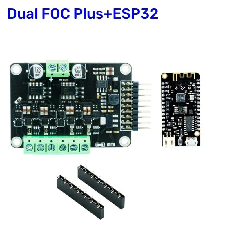
I’m trying to control two small 24V BLDC pumps. I thought this SimpleFOC 3.2 Shield MKS Dual module from Amazon would work.
The pumps don’t have encoders. My understanding is that I can use the current sensor on the FOC module to adjust the speed. I don’t need to be able to control absolute speed, just relative speed once I see how much water its pumping at some setting. Am I correct about using the current sensor on the FOC module for reliable speed control?
Looking deeper on how the current sensor is instantiated in the Arduino code example, I see it seems to expect A0 and A1 pins on the ESP32 for current sensing.
LowsideCurrentSense current_sense = LowsideCurrentSense(shunt_resistor, gain, A0, A1); // when measuring A and B phase currents and not measuring C
The ESP32 microcontroller is connecting to the FOC module over I2C (so just connecting SCL, SDA, gnd, 3.3V). It doesn’t seem like I’m meant to connect analog pins from the ESP32 to the FOC module to get current sensor data? Or have I misunderstood? The FOC v3.2 module has onboard current sensor already. I should be able to grab the current via I2C data?
Maybe I’m following the wrong Arduino code from an older version of FOC? One that assumes my application microcontroller has the current rather than the FOC module?
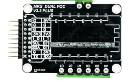
“Current sensing: ±33A On-line current detection: (1mR resistor for example)”
Onboard high precision current sensor.