Hi.
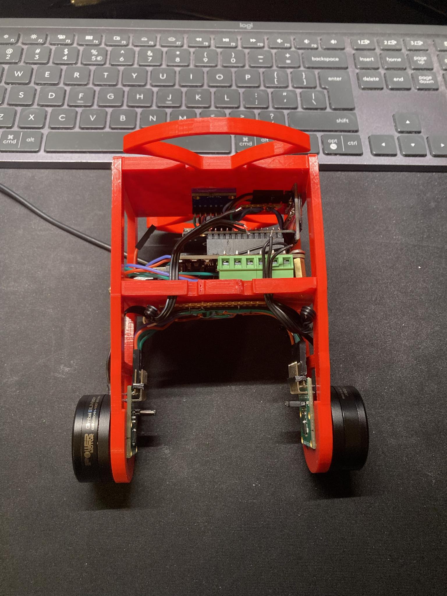
Today, the missing element finally arrived and I was able to return to the robot. I adjusted the Arduino-FOC-balancer code to fit my needs. Unfortunately, the robot, as shown in the video, did not work well. Maybe you have suggestions on what’s not working properly

#include <SimpleFOC.h>
#include "imu_helpers.h"
#include "BluetoothSerial.h"
BluetoothSerial bluetooth;

BLDCMotor motor1 = BLDCMotor(7);
BLDCDriver3PWM driver1 = BLDCDriver3PWM(32, 33, 25, 22);
MagneticSensorSPI encoder1 = MagneticSensorSPI(AS5147_SPI, 15); //- R

BLDCMotor motor2 = BLDCMotor(7);
BLDCDriver3PWM driver2 = BLDCDriver3PWM(26, 27, 14, 12);
MagneticSensorSPI encoder2 = MagneticSensorSPI(AS5147_SPI, 5); // - L

PIDController pid_stb{.P = 30, .I = 100, .D = 1, .ramp = 100000, .limit = 7};
PIDController pid_vel{.P = 0.01, .I = 0.03, .D = 0, .ramp = 10000, .limit = _PI / 10};
LowPassFilter lpf_pitch_cmd{.Tf = 0.07};
LowPassFilter lpf_throttle{.Tf = 0.5};
LowPassFilter lpf_steering{.Tf = 0.1};

float steering = 0;
float throttle = 0;
float max_throttle = 10; // 20 rad/s
float max_steering = 1;  // 1 V
int state = 1;           // 1 on / 0 off

Commander commander = Commander(Serial);
void cntStab(char *cmd) { commander.pid(&pid_stb, cmd); }
void cntMove(char *cmd) { commander.pid(&pid_vel, cmd); }
void lpfPitch(char *cmd) { commander.lpf(&lpf_pitch_cmd, cmd); }
void lpfSteering(char *cmd) { commander.lpf(&lpf_steering, cmd); }
void lpfThrottle(char *cmd) { commander.lpf(&lpf_throttle, cmd); }

void setup()
{
    Serial.begin(250000);

    _delay(1000);
    if (!initIMU())
    {
        Serial.println(F("IMU connection problem... Disabling!"));
        return;
    }
    _delay(1000);

    encoder1.init();
    encoder2.init();

    motor1.linkSensor(&encoder1);
    motor2.linkSensor(&encoder2);

    driver1.voltage_power_supply = 4;
    driver1.init();
    motor1.linkDriver(&driver1);
    driver2.voltage_power_supply = 4;
    driver2.init();
    motor2.linkDriver(&driver2);

    motor1.controller = MotionControlType::torque;
    motor2.controller = MotionControlType::torque;

    motor1.useMonitoring(Serial);
    motor2.useMonitoring(Serial);

    motor1.init();
    motor2.init();

    motor1.initFOC();
    motor2.initFOC();

    commander.add('A', cntStab, "pid stab");
    commander.add('B', cntMove, "pid vel");
    commander.add('C', lpfThrottle, "lpf vel command");
    commander.add('D', lpfPitch, "lpf throttle");
    commander.add('E', lpfSteering, "lpf steering");

    Serial.println(F("Balancing robot ready!"));
}

void loop()
{
    motor1.loopFOC();
    motor2.loopFOC();

    motor1.move();
    motor2.move();

    if (!state)
    {
        motor1.target = 0;
        motor2.target = 0;
    }
    else if (hasDataIMU())
    {
        float pitch = getPitchIMU();
        float target_pitch = lpf_pitch_cmd(pid_vel((motor1.shaft_velocity + motor2.shaft_velocity) / 2 - lpf_throttle(throttle)));
        float voltage_control = pid_stb(target_pitch - pitch);
        float steering_adj = lpf_steering(steering);
        motor1.target = voltage_control + steering_adj;
        motor2.target = voltage_control - steering_adj;
    }

    commander.run();
    handleBluetooth(bluetooth);
}

void handleBluetooth(Stream &bt_port)
{
    int inByte;
    if (bt_port.available() > 0)
    {
        while (bt_port.available())
        {
            inByte = bt_port.read();
        }
        inByte = inByte - 100;
        if (inByte == 155)
        {
            steering = 0;
            throttle = 0;
            state = 1;
        }
        else if (inByte == 154)
        {
            steering = 0;
            throttle = 0;
            state = 0;
        }
        else if (inByte >= -100 && inByte <= 100)
        {
            throttle = max_throttle * ((float)inByte) / 100.0;
        }
        else if (inByte >= 110 && inByte <= 150)
        {
            steering = max_steering * ((float)(inByte - 130.0)) / 20.0;
        }
        else
        {
            steering = 0;
            throttle = 0;
        }
        bt_port.flush();
    }
}
serial port:
Initializing I2C devices...
Testing device connections...
MPU6050 connection successful
Initializing DMP...
>......
-2302.00000,    -2333.00000,    1532.00000,     151.00000,      101.00000,      40.00000

Enabling DMP...
DMP ready! Waiting for first interrupt...
Adjusting DMP sensor fusion gain...
MOT: Monitor enabled!
MOT: Monitor enabled!
MOT: Init
MOT: Enable driver.
MOT: Init
MOT: Enable driver.
MOT: Align sensor.
MOT: sensor_direction==CW
MOT: PP check: fail - estimated pp: 18.06
MOT: Zero elec. angle: 1.86
MOT: No current sense.
MOT: Ready.
MOT: Align sensor.
MOT: sensor_direction==CCW
MOT: PP check: fail - estimated pp: 1.08
MOT: Zero elec. angle: 1.83
MOT: No current sense.
MOT: Ready.
Balancing robot ready!
[ 22552][E][Wire.cpp:513] requestFrom(): i2cRead returned Error 263
[ 39614][E][Wire.cpp:513] requestFrom(): i2cRead returned Error 263
[ 61501][E][Wire.cpp:513] requestFrom(): i2cRead returned Error 263
The error “i2cRead returned Error” is worrying me
I added i2c configuration to the imou _helpers file
int initIMU() {
  Wire.begin(0, 4);
  Wire.setClock(400000); // 400kHz I2C clock. Comment this line if having compilation difficulties
...
I use a 9V 800mA power supply, and I’m wondering if the power supply might be the problem.