Apart from the ADC, I don’t see any issues with the core concept. I have a few questions and comments.
Question: How did you calculate the value of Rp?
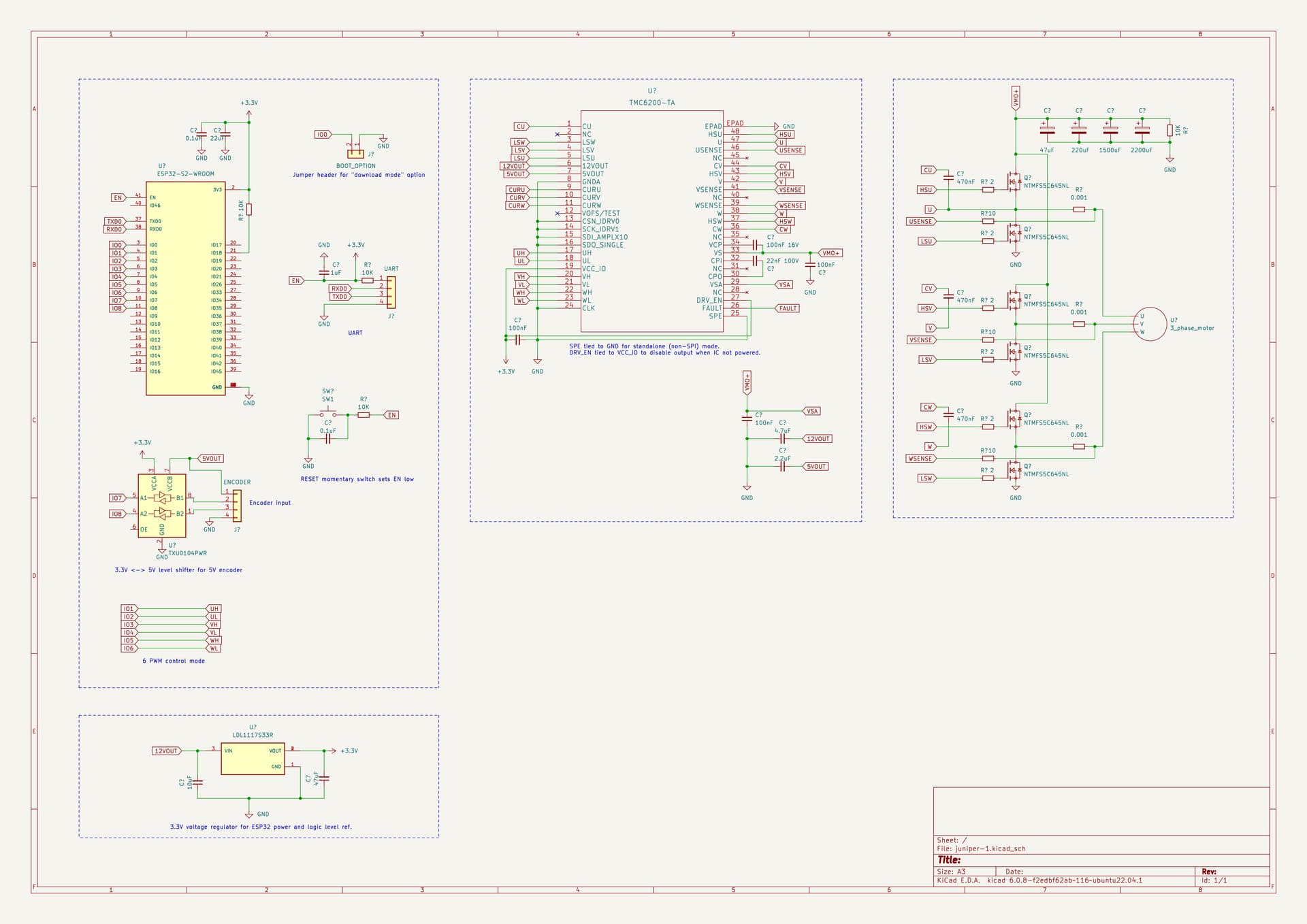
Question: You got a bunch of hodge-podge capacitors here:
Why are they so different? Any grand idea behind that designs decision? If not, please stick to a couple snubbers / strategically placed decouples, plus some reasonable bulk capacitance of the same size. Your BOM will thank you later.
Comment / Question: What is that R1 doing there? If you are trying to build an input low-pass RC filter, that 10k is meaningless. If you are trying to use it for bulk capacitance discharge when you turn off the power, that 10k is way too low, you will need something over 100k, and large enough footprint to absorb the power you will be pumping into when your circuit is on. If the latter, I’d remove it altogether because your circuit will absorb the buffer very quickly anyways. If the former, to paraphrase Obi-Wan, you need to go back and rethink your filter design.
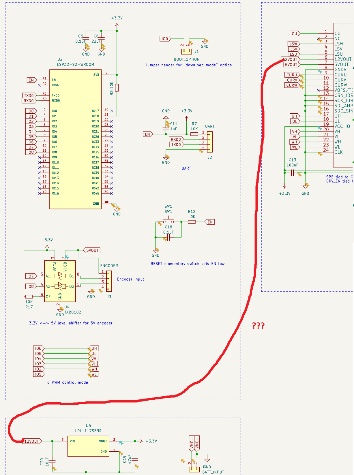
Comment: If I understand correctly you are thinking of doing this:
That is a Bad Idea™. Why? Because you will be:
- Chaining an LDO to another LDO which already has an LDO attached to it (the 5V internal).
- LDOs are notoriously inefficient and you will overheat your driver.
- Divert the 12V power away from the gate driver to an external and kill the driver.
- Underpower the ESP32 which is notoriously power hungry because as I said it’s not really an MCU but WIFI chip and when used as such it requires huge amounts of power.
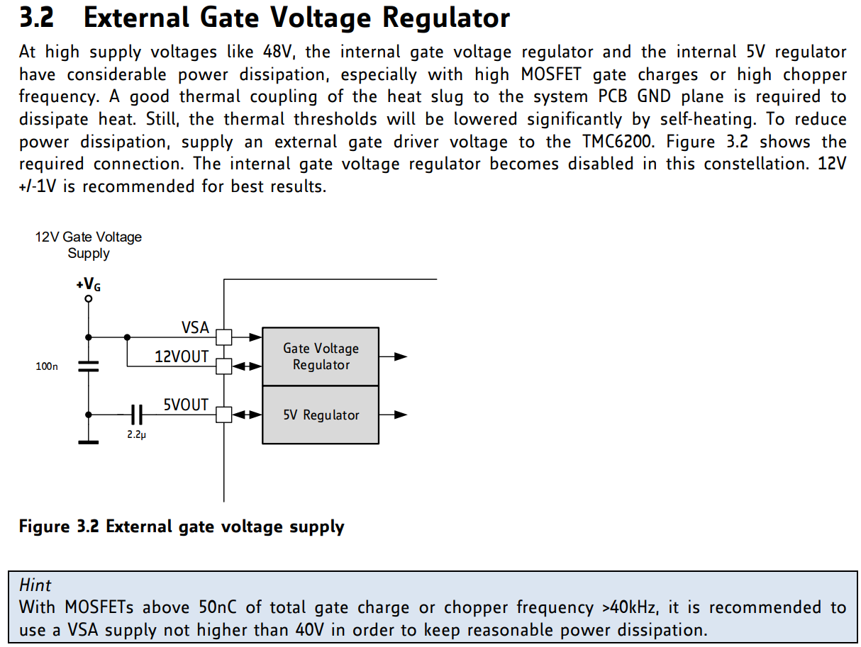
This is perhaps the biggest design flaw of the schematics. I would instead add a buck step-down converter from VMO+ to 11.5V, hook THAT converter to the 12V to supply extra power to the driver, and this will turn off the internal driver LDO and improve heat management. Then, I will attach the LDL1117 to this external buck step-down, and then the ESP32 to the external LDO. Then re-work the schematics as the specs are advising:
You can borrow/get a very cheap buck step down design from my Lepton design. See how I did it there. You need to be a little careful because I believe I did drop to a little above 11V but still, please double check my design.
Last, I see you use the 5VOUT to power a level shifter. Again, do not use the 5V of the driver, these are for internal driver consumption. Use another LDO to drop the 11.5V from the external buck converter to 5V, then use that to drive whatever else you need. Same reasoning as above.
I hope my comments/suggestions are helping you.
Cheers,
Valentine