RP2350 support (Raspberry Pico 2)

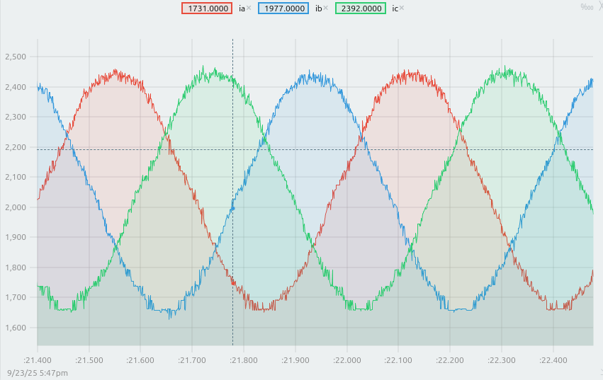
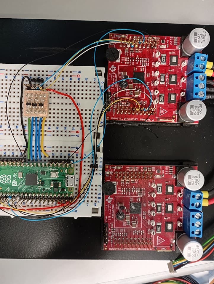
Hi, I think the current reading PR is in an acceptable stage for a first review, and I’m happy to send a proto board with the 3 ADC if someone (preferably in France) is interested in testing it.

As another topic, I’m now considering working on implementing RPxxxxHWEncoder library to read quadrature encoders. This should be fairly simple since Raspberry Pi provide an example: pico-examples/pio/quadrature_encoder/quadrature_encoder.pio at master · raspberrypi/pico-examples · GitHub It just needs to be optimized for non-blocking read of the count register.

Before starting, I just wanted to ask if there were already an ongoing work to address this ?

AFAIK there’s an existing PIO based library which people may have been using with our GenericSensor…

But I think it would be great to have a „native“ one in the drivers library :slight_smile:

Hi, I’ll have to stop working on this for a few weeks, so I figured I could give some feedback on the current state.

I’m now controlling a motor (open loop velocity) via a BOOSTXL-DRV8323 and monitoring the output current:

The noise probably comes from my not ideal setup, but that’s a good start:

My plan is to first fix some ringing issue with the boostxl by tuning gate driving parameters, and then switch to close loop current control.

I also want to think about multiple axis setup with more ADC in parallel, and how the library should handle it. The RP2350 should have no issue driving 2 or (3,4?) motors, making it quite nice for some applications.

I’m considering using more state machine with the same PIO program if we want to interleave the PWMs (but at the cost of 1clk and 1cs lines per additional motors), or keep them all in sync and save few pins.

I’ll try to benchmark more and report here for multi axis.

It’s a very good result I think. Congratulations!

I am trying to implement the MXLEMMINGObserverSensor.
I have modified my hardware design. Now I am using 2 x current Linear Hall-effect current sensor (MCS1802 w/isolated voltage output), ADC3 for phase U (first phase), and ADC2 for phase W (third phase).
I have also a setup where I use 6 PWM signals UH/UL , VH/VL and WH/WL.

// ===== Pins (RP2040 Pico 2 W) =====
#define UH_PIN 16
#define UL_PIN 17
#define VH_PIN 18
#define VL_PIN 19
#define WH_PIN 20
#define WL_PIN 21

#define VOLTAGE_ADC_PIN 26 // ADC0 (bus voltage divider)
#define PHASE_W_ADC_PIN 27 // ADC1 (MCS1802 phase W)
#define PHASE_U_ADC_PIN 28 // ADC2 (MCS1802 phase U)

Anyone who have made as similar example?