Thanks for your feedback,
I think you are right. The ADC is probably too slow.
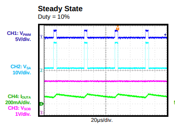
When I first read the MP6541 datasheet, It was not clear to me what the analog output really was, since on the graphs, it seems that the current sensing is not modulated by the PWM, so that it would behave more like inline sensing.
Then the current sense section says:
Current-Sense Amplifiers
The internal current-sensing circuits detect the
current flowing in each of the three outputs. An
output pin for each phase sources or sinks a
current that is proportional to the current flowing
in each phase. It should be noted that only the
current flowing in the LS-FET is sensed in both
the forward and reverse directions
This is really not clear.
I think I will move away from both this ADC and the MP6541. It is hard to find a suitable ADC and going one 12 bits SAR per channel is a better idea. I wanted to evaluate the MP6541 to have a very compact design, but that is another sorry, I should keep the two project separated.
To keep the design compact still, since the PIO let us do deterministic data transfer, we could even choose a simpler SAR ADC where the conversion rate and logic is linked to the data transfer.
For example, with the BU79100G-LA (6pins 2.9 mm x 2.8 mm x 1.25 mm):
The maximum SPI frequency is 20Mhz, it needs 16 clock cycles to do the conversion and transfer, so a latency of 0.8 uS.
Thanks to the PIO again, we can use only 5 GPIO to do 3 current sensing (share CLK and CS + one data input per channel).
What do you think?
I have some BOOSTXL-DRV8323RX that I could use as power stage, and focus on the pico2 + ADC part.
Best,
Thomas.