RP2040 with AS5048A

Thanks @runger, this is the code, which now compiles on arduino IDE but not on platformio. But also sends me 00,0 on terminal. The wiring is absolutely sure is ok, and connected to SPI0 on pico.

#include "Arduino.h"
#include "Wire.h"
#include "SPI.h"
#include "SimpleFOC.h"
#include "SimpleFOCDrivers.h"
#include "encoders/as5048a/MagneticSensorAS5048A.h"


// these are GPIO numbers, so pin 13 is the one labeled GPIO13 on the board
#define PIN_CS 22 //13
#define PIN_CLK 18 //10
#define PIN_MISO 16 //12
#define PIN_MOSI 19 //11

arduino::MbedSPI mySPI(PIN_MISO, PIN_MOSI, PIN_CLK);
MagneticSensorSPIConfig_s myAS5048_SPI = {
  .spi_mode = SPI_MODE1,
  .clock_speed = 1000000,
  .bit_resolution = 14,
  .angle_register = 0x3FFF,
  .data_start_bit = 13,
  .command_rw_bit = 14,
  .command_parity_bit = 15
};
MagneticSensorSPI sensor = MagneticSensorSPI(myAS5048_SPI, PIN_CS);

void setup() {
  // monitoring port
  Serial.begin(115200);
  sensor.init(&mySPI);
}

void loop() {
  // iterative function updating the sensor internal variables
  // it is usually called in motor.loopFOC()
  // this function reads the sensor hardware and 
  // has to be called before getAngle nad getVelocity
  sensor.update();
  // display the angle and the angular velocity to the terminal
  Serial.print(sensor.getAngle());
  Serial.print("\t");
  Serial.println(sensor.getVelocity());
  delay(100); // 10x per second is enough for printing the angle. remove the delay when actually running a motor

Can you post your platformio.ini? The problem is probably here if it is compiling on Arduino IDE

Sure, here it is.

; PlatformIO Project Configuration File
;
;   Build options: build flags, source filter
;   Upload options: custom upload port, speed and extra flags
;   Library options: dependencies, extra library storages
;   Advanced options: extra scripting
;
; Please visit documentation for the other options and examples
; https://docs.platformio.org/page/projectconf.html

[env:pico]
platform = raspberrypi
board = pico
framework = arduino
lib_archive = false
monitor_speed = 115200
lib_deps = 
	askuric/Simple FOC@^2.3.0
	simplefoc/SimpleFOCDrivers@^1.0.4

Very strange, second times compiles without error, but with 7 problems.

@runger Could you please take a look at this:

I decided to return to a previous code, and installed a different board with board manager in IDE. This board is exactly the same, what I’m using, the Wiznet W6100-EVB-pico.

The compiler throws this errors for this kind of pico, but with a regular pico runs without errors. Maybe here is the problem with the SPI.

This is the code:

#include "Arduino.h"
#include "Wire.h"
#include "SPI.h"
#include "SimpleFOC.h"
#include "SimpleFOCDrivers.h"
#include "encoders/as5048a/MagneticSensorAS5048A.h"

#define SENSOR1_CS 22 // some digital pin that you're using as the nCS pin
MagneticSensorAS5048A sensor1(SENSOR1_CS);


void setup() {
    sensor1.init();
}

void loop() {
// update the sensor (only needed if using the sensor without a motor)
    sensor1.update();

    // get the angle, in radians, including full rotations
    float a1 = sensor1.getAngle();
Serial.print(a1);
    // get the velocity, in rad/s - note: you have to call getAngle() on a regular basis for it to work
    float v1 = sensor1.getVelocity();

    // get the angle, in radians, no full rotations
    float a2 = sensor1.getCurrentAngle();

    // get the raw 14 bit value
    uint16_t raw = sensor1.readRawAngle();

    // read the CORDIC magnitude value, a measure of the magnet field strength
    float m1 = sensor1.readMagnitude();

    // check for errors
    if (sensor1.isErrorFlag()) {
        AS5048Error error = sensor1.clearErrorFlag();
        if (error.parityError) { // also error.framingError, error.commandInvalid
            // etc...            
        }
    }

}

And the errors:

/Users/m2mini/Documents/Arduino/libraries/Simple_FOC/src/current_sense/hardware_specific/rp2040/rp2040_mcu.cpp:18:44: error: ‘ADC_CS_START_ONCE_BITS’ was not declared in this scope

  • 18 | alignas(32) const uint32_t trigger_value = ADC_CS_START_ONCE_BITS; // start once*
  •  |                                            ^~~~~~~~~~~~~~~~~~~~~~*
    

/Users/m2mini/Documents/Arduino/libraries/Simple_FOC/src/current_sense/hardware_specific/rp2040/rp2040_mcu.cpp: In member function ‘bool RP2040ADCEngine::init()’:
/Users/m2mini/Documents/Arduino/libraries/Simple_FOC/src/current_sense/hardware_specific/rp2040/rp2040_mcu.cpp:148:5: error: ‘adc_init’ was not declared in this scope

  • 148 | adc_init();*
  •  |     ^~~~~~~~*
    

/Users/m2mini/Documents/Arduino/libraries/Simple_FOC/src/current_sense/hardware_specific/rp2040/rp2040_mcu.cpp:153:13: error: ‘adc_gpio_init’ was not declared in this scope; did you mean ‘pio_gpio_init’?

  • 153 | adc_gpio_init(i+26);*
  •  |             ^~~~~~~~~~~~~*
    
  •  |             pio_gpio_init*
    

/Users/m2mini/Documents/Arduino/libraries/Simple_FOC/src/current_sense/hardware_specific/rp2040/rp2040_mcu.cpp:158:5: error: ‘adc_set_round_robin’ was not declared in this scope

  • 158 | adc_set_round_robin(enableMask);*
  •  |     ^~~~~~~~~~~~~~~~~~~*
    

/Users/m2mini/Documents/Arduino/libraries/Simple_FOC/src/current_sense/hardware_specific/rp2040/rp2040_mcu.cpp:159:5: error: ‘adc_fifo_setup’ was not declared in this scope

  • 159 | adc_fifo_setup(*
  •  |     ^~~~~~~~~~~~~~*
    

/Users/m2mini/Documents/Arduino/libraries/Simple_FOC/src/current_sense/hardware_specific/rp2040/rp2040_mcu.cpp:169:9: error: ‘adc_set_clkdiv’ was not declared in this scope; did you mean ‘pwm_set_clkdiv’?

  • 169 | adc_set_clkdiv(0);*
  •  |         ^~~~~~~~~~~~~~*
    
  •  |         pwm_set_clkdiv*
    

/Users/m2mini/Documents/Arduino/libraries/Simple_FOC/src/current_sense/hardware_specific/rp2040/rp2040_mcu.cpp:172:9: error: ‘adc_set_clkdiv’ was not declared in this scope; did you mean ‘pwm_set_clkdiv’?

  • 172 | adc_set_clkdiv(48000000/samples_per_second);*
  •  |         ^~~~~~~~~~~~~~*
    
  •  |         pwm_set_clkdiv*
    

/Users/m2mini/Documents/Arduino/libraries/Simple_FOC/src/current_sense/hardware_specific/rp2040/rp2040_mcu.cpp:185:10: error: ‘adc_hw’ was not declared in this scope

  • 185 | &adc_hw->fifo, // source*
  •  |          ^~~~~~*
    

/Users/m2mini/Documents/Arduino/libraries/Simple_FOC/src/current_sense/hardware_specific/rp2040/rp2040_mcu.cpp: In member function ‘void RP2040ADCEngine::start()’:
/Users/m2mini/Documents/Arduino/libraries/Simple_FOC/src/current_sense/hardware_specific/rp2040/rp2040_mcu.cpp:226:13: error: ‘adc_select_input’ was not declared in this scope

  • 226 | adc_select_input(i); // set input to first enabled channel*
  •  |             ^~~~~~~~~~~~~~~~*
    

/Users/m2mini/Documents/Arduino/libraries/Simple_FOC/src/current_sense/hardware_specific/rp2040/rp2040_mcu.cpp:235:5: error: ‘adc_run’ was not declared in this scope

  • 235 | adc_run(true);*
  •  |     ^~~~~~~*
    

/Users/m2mini/Documents/Arduino/libraries/Simple_FOC/src/current_sense/hardware_specific/rp2040/rp2040_mcu.cpp: In member function ‘void RP2040ADCEngine::stop()’:
/Users/m2mini/Documents/Arduino/libraries/Simple_FOC/src/current_sense/hardware_specific/rp2040/rp2040_mcu.cpp:243:5: error: ‘adc_run’ was not declared in this scope

  • 243 | adc_run(false);*
  •  |     ^~~~~~~*
    

/Users/m2mini/Documents/Arduino/libraries/Simple_FOC/src/current_sense/hardware_specific/rp2040/rp2040_mcu.cpp:247:5: error: ‘adc_fifo_drain’ was not declared in this scope

  • 247 | adc_fifo_drain();*
  •  |     ^~~~~~~~~~~~~~*
    

exit status 1

Compilation error: exit status 1
This error has already been fixed, IIRC, but you have to use the dev branch version of the library, IIRC.
Or wait for the next release version, which will include the fix…

Sorry for the noob question but where is located the dev branch version of the library?

This is the DEV?

Almost there…

I have now an arduino ide error with the dev version, which seems to be in 2.1.1 but the same in 2.1.2 nigtly.

Property 'upload.tool.serial' is undefined

Yes, you found it!

This error should not really happen - you can install the dev version by replacing the default version of the library, which should be in your Documents/Arduino/libraries folder.

I think this error is not related to the simpleFOC library, this is a known error from arduino IDE 2.1, but I can not upload the code.

Finally, I’ve got the sensor signal. Here is the working code:

#include "Arduino.h"
#include "SPI.h"
#include "SimpleFOC.h"
#include "SimpleFOCDrivers.h"
#include "encoders/as5048a/MagneticSensorAS5048A.h"

#define SPI_2_MISO  12
#define SPI_2_MOSI  15
#define SPI_2_SCK   14
#define SENSOR1_CS  13 // some digital pin that you're using as the nCS pin

MagneticSensorAS5048A sensor1(SENSOR1_CS, true);
MbedSPI spi2(SPI_2_MISO, SPI_2_MOSI, SPI_2_SCK);


void setup() {
  spi2.begin();
  sensor1.init(&spi2);


}

void loop() {
 // update the sensor (only needed if using the sensor without a motor)
  sensor1.update();

  // get the angle, in radians, including full rotations
  float a1 = sensor1.getAngle();
  Serial.println(a1);
  // get the velocity, in rad/s - note: you have to call getAngle() on a
  // regular basis for it to work
  float v1 = sensor1.getVelocity();
  // get the angle, in radians, no full rotations
  float a2 = sensor1.getCurrentAngle();
  // Serial.println(a2);
  //  get the raw 14 bit value
  uint16_t raw = sensor1.readRawAngle();
  // read the CORDIC magnitude value, a measure of the magnet field strength
  float m1 = sensor1.readMagnitude();
  // check for errors
  if (sensor1.isErrorFlag()) {
    AS5048Error error = sensor1.clearErrorFlag();
    if (error.parityError) { // also error.framingError, error.commandInvalid
                             // etc...
    }
  }
}
3 Likes

Hi guys.

Sorry to dig this up but I’m having some trouble with a very similar setup. I’m using the Raspberry pi pico with the Earle Philhower core and getting the same error message with the SPI.

error: no matching function for call to ‘arduino::HardwareSPI::HardwareSPI(int, int, int)’

#include "Arduino.h"
#include <SimpleFOC.h>
#include "Wire.h"
#include "SPI.h"
#include "SimpleFOCDrivers.h"

// MagneticSensorSPI(int cs, float _cpr, int _angle_register)
// cs              - SPI chip select pin 
// bit_resolution  - sensor resolution
// angle_register  - (optional) angle read register - default 0x3FFF
//MagneticSensorSPI as5047u = MagneticSensorSPI(10, 14, 0x3FFF);
// or quick config

BLDCMotor motor = BLDCMotor(7);

#define PIN_CS 13
#define PIN_CLK 10
#define PIN_MISO 12
#define PIN_MOSI 11
SPIClass mySPI(PIN_MOSI, PIN_MISO, PIN_CLK);
MagneticSensorSPIConfig_s myAS5147_SPI = {
  .spi_mode = SPI_MODE1,
  .clock_speed = 1000000,
  .bit_resolution = 14,
  .angle_register = 0x3FFF,
  .data_start_bit = 13,
  .command_rw_bit = 14,
  .command_parity_bit = 15
};


I’ve tried the way runger suggested above and I’m not sure what to do next.

I’m using a AS5147U magnetic sensor and the same setup was working well on an Arduino mega. The problem I’ve run into is I don’t know how to declare what pins the SPI uses in the code.

  • Update, I’ve got so far as to have the chip select working. I have each channel of the SPI on my oscilloscope.

Here’s the code I’m trying to get working:

#include <SimpleFOC.h>
#include "SPI.h"
//#include "SimpleFOCDrivers.h"

// MagneticSensorSPI(int cs, float _cpr, int _angle_register)
// cs              - SPI chip select pin 
// bit_resolution  - sensor resolution
// angle_register  - (optional) angle read register - default 0x3FFF
//MagneticSensorSPI as5047u = MagneticSensorSPI(10, 14, 0x3FFF);
// or quick config

BLDCMotor motor = BLDCMotor(7);
/*
#define PIN_CS 13
#define PIN_CLK 10
#define PIN_MISO 12
#define PIN_MOSI 11
SPIClass mySPI(PIN_MOSI, PIN_MISO, PIN_CLK);
MagneticSensorSPIConfig_s myAS5147_SPI = {
  .spi_mode = SPI_MODE1,
  .clock_speed = 1000000,
  .bit_resolution = 14,
  .angle_register = 0x3FFF,
  .data_start_bit = 13,
  .command_rw_bit = 14,
  .command_parity_bit = 15
};
*/


#define PIN_CS 13
#define PIN_CLK 10
#define PIN_MISO 12
#define PIN_MOSI 11

SPISettings spisettings(1000000, MSBFIRST, SPI_MODE1);

bool setRX(12); // or setMISO()
bool setCS(13);
bool setSCK(10);
bool setTX(11); // or setMOSI()

MagneticSensorSPI sensor = MagneticSensorSPI(AS5147_SPI, 13);

// BLDCDriver3PWM(pwmA, pwmB, pwmC, (en optional))
BLDCDriver3PWM driver = BLDCDriver3PWM(7, 9, 6, 8);


float target_angle = 0;
// instantiate the commander
Commander command = Commander(Serial);
void onTarget(char* cmd){ command.scalar(&target_angle, cmd); }


void setup() {

  // use monitoring with serial 
  Serial.begin(115200);
  //SPI.begin();
  //sensor.init(&mySPI);
  sensor.init();
  // enable more verbose output for debugging
  // comment out if not needed
  SimpleFOCDebug::enable(&Serial);

  // driver config
  // power supply voltage [V]
  driver.voltage_power_supply = 20;
  // limit the maximal dc voltage the driver can set
  // as a protection measure for the low-resistance motors
  // this value is fixed on startup
  driver.voltage_limit = 10;
  if(!driver.init()){
    Serial.println("Driver init failed!");
    return;
  }

  motor.linkSensor(&sensor);

  // link the motor and the driver
  motor.linkDriver(&driver);

 
  motor.controller = MotionControlType::angle;
  
  // controller configuration based on the control type 
  // velocity PI controller parameters
  // default P=0.5 I = 10
  motor.PID_velocity.P = 0.2;
  motor.PID_velocity.I = 20;
  // jerk control using voltage voltage ramp
  // default value is 300 volts per sec  ~ 0.3V per millisecond
  motor.PID_velocity.output_ramp = 1000;
  
  //default voltage_power_supply
  motor.voltage_limit = 6;

  // velocity low pass filtering
  // default 5ms - try different values to see what is the best. 
  // the lower the less filtered
  motor.LPF_velocity.Tf = 0.01;

  // angle P controller 
  // default P=20
  motor.P_angle.P = 20;
  //  maximal velocity of the position control
  // default 20
  motor.velocity_limit = 4;
  
  // initialize motor
  motor.init();
  // align encoder and start FOC
  motor.initFOC();

  // add target command T
  command.add('T', onTarget, "target angle");

  // monitoring port
  Serial.begin(115200);
  Serial.println("Motor ready.");
  Serial.println("Set the target angle using serial terminal:");
  _delay(1000);
}

void loop() {
  // main FOC algorithm function
  motor.loopFOC();

  // Motion control function
  motor.move();

  // user communication
  command.run();
}

Hey,

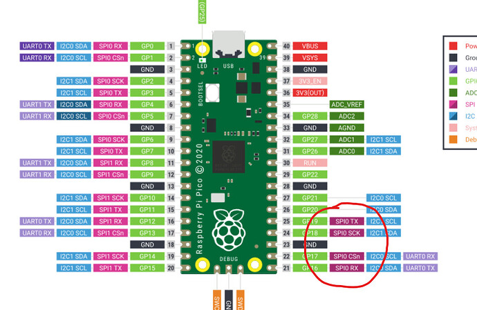
Only certain pins can be used for SPI, I assume you checked them against a pin out diagram?

Have you tried to use the dedicated AS5047U driver we have in the drivers library? It will let you use this sensors advanced features…

It does sound like your issues are related to the SPI setup though, and it looks to me like you’re close.

I have got it working!

The problem was which SPI pins I was using there. I thought I could just use any of the SPI capable pins if I configured them in the setup. However testing around it seems the SPI was being output on the Pi Picos default SPI pins despite me trying to set other ones.

As for the sensor, it seems to work as is. I haven’t had a look at the AS5047U drive yet. Seems like the AS5047U and AS5147U are pretty similar. I think the AS5147U board was the only one I could find at mouser.

Here is the code using the AS5147U on the Pi Pico with Earle Philhower’s core, for future reference.

#include <SimpleFOC.h>
#include "SPI.h"


BLDCMotor motor = BLDCMotor(7);

MagneticSensorSPI sensor = MagneticSensorSPI(AS5147_SPI, 17);

// BLDCDriver3PWM(pwmA, pwmB, pwmC, (en optional))
BLDCDriver3PWM driver = BLDCDriver3PWM(7, 9, 6, 8);

float target_angle = 0;
// instantiate the commander
Commander command = Commander(Serial);
void onTarget(char* cmd){ command.scalar(&target_angle, cmd); }

void setup() {

  // use monitoring with serial 
  Serial.begin(115200);
  //SPI.begin();
  //sensor.init(&mySPI);
  sensor.init();
  // enable more verbose output for debugging
  // comment out if not needed
  SimpleFOCDebug::enable(&Serial);

  // driver config
  // power supply voltage [V]
  driver.voltage_power_supply = 20;
  // limit the maximal dc voltage the driver can set
  // as a protection measure for the low-resistance motors
  // this value is fixed on startup
  driver.voltage_limit = 10;
  if(!driver.init()){
    Serial.println("Driver init failed!");
    return;
  }

  motor.linkSensor(&sensor);

  // link the motor and the driver
  motor.linkDriver(&driver);

 
  motor.controller = MotionControlType::angle;
  
  // controller configuration based on the control type 
  // velocity PI controller parameters
  // default P=0.5 I = 10
  motor.PID_velocity.P = 0.2;
  motor.PID_velocity.I = 20;
  // jerk control using voltage voltage ramp
  // default value is 300 volts per sec  ~ 0.3V per millisecond
  motor.PID_velocity.output_ramp = 1000;
  
  //default voltage_power_supply
  motor.voltage_limit = 6;

  // velocity low pass filtering
  // default 5ms - try different values to see what is the best. 
  // the lower the less filtered
  motor.LPF_velocity.Tf = 0.01;

  // angle P controller 
  // default P=20
  motor.P_angle.P = 20;
  //  maximal velocity of the position control
  // default 20
  motor.velocity_limit = 4;
  
  // initialize motor
  motor.init();
  // align encoder and start FOC
  motor.initFOC();

  // add target command T
  command.add('T', onTarget, "target angle");

  // monitoring port
  Serial.begin(115200);
  Serial.println("Motor ready.");
  Serial.println("Set the target angle using serial terminal:");
  _delay(1000);
}

void loop() {
  // main FOC algorithm function
  motor.loopFOC();

  // Motion control function
  motor.move();

  // user communication
  command.run();
}
3 Likes