Have been working on this for some time. Think 2. revision is getting ready for testing. Just wanted to share some progress. When tested and ready for DIY, I plan to sell the design/print files for a modest $, maybe inject-mold the gears at some point. “Gear Box” will be fully sealed, to avoid dust and grime from messing with gears and grease.
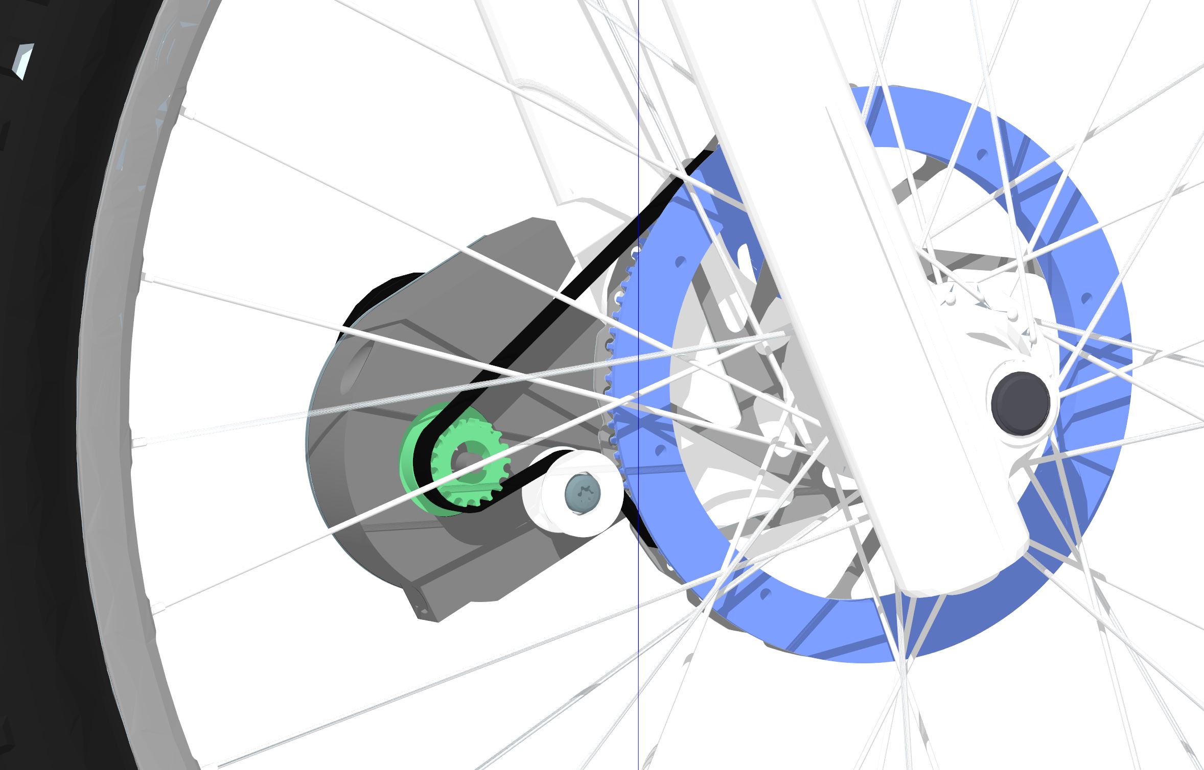
Have sketched up a tension bracket for the belt. This way, it is more straightforward to take off the belt, when and if the bike runs out of power. It will of course also insure a tight belt.
I found that we need a 665mm belt, which is 8.5 euro on Misumi
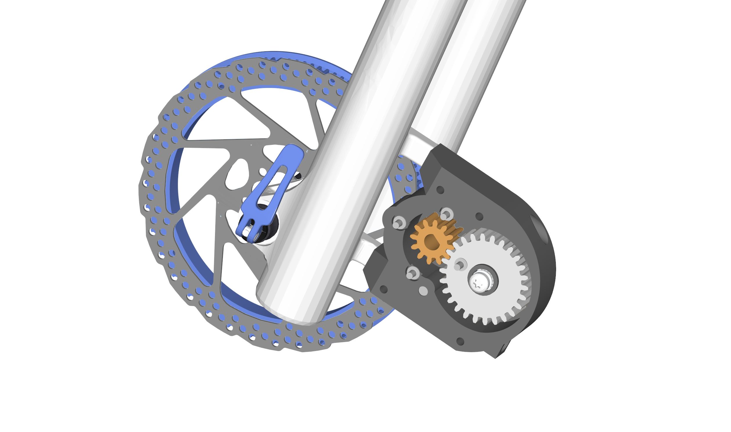
Opted for GT4 8mm (pitch) 12mm (width) belt´s. They should have a 25% improved load capacity compared to GT3. Furthermore the 12mm compared to 9mm will increase performance. There is a open question though. Gates advises to use a minimum of 22 grooves for pulley. I will use 14, but because the tensioner / idler compresses the belt around the teeth, I suppose the contact of groves will be close to a larger pulley without idler. I do not see the belt slipping on those large teeth/grooves. Do you think the belt will have a hard time to bend around 14 tooth pulley. Overall gear-ratio will be 1 : 10.8. Im going for a slight increase in top speed at the expense of acceleration (140 kv). The normal use case will not come close to the belt´s load capacity.
Edid: On a 29 inch wheel I think a 200mm disc is more suitable compared to the 180mm im working on. This will most likely even out the difference in wheel size vs. gear-ratio. Some front forks are build for 200mm disc´s, while some need a spacer.
I dont know the final price. When the concept i ready, I will do a Kickstarter. Making a community order will cut the price. I payed around 100 for two pcs at my local CO2 laser cutter. If ordering from a industrial supplier I think the price might come down to 20-30$ a peace.
Making the gear housing in aluminium, that’s another matter. This would require a tool/mold and large quantities. I believe a 3D print can be strong enough. PLA will warp in the heat though, and nylon is hard to print. PETG is a good candidate.
[Edit] I plan to mount the plate to my openPnP machine, and run it on 24v psu. Need to get a hold of some magnetic angle sensors for that.
But if you have a top and bottom plate in steel, couldn’t you mount the gears to that using some bolts, bushings and bearings? Those parts are available pre-made and cheaply, and then you would not need a mold?
What I meant was, if you want to inject cast the box in aluminum, it’s expensive. Or you can CNC it. Was just thinking how to scale it. The top plate will hold the drivetrain axis, so it should be strong.