Regenerative Braking

It wouldn’t need to be on the same timer as the Motor control timer. Most MCUs has a few timers and a pin we don’t use, so I don’t see that as a problem, but there may be extreme cases.

I agree with your observations. The extra regen circuit proposed puts a unnecessary layer of complexity in the equation. If the method you described earlier in the thread, taken from that research paper works, then it works and would need confirmation.

In the case of a light_EV or eMTB I think a brake resistor is a good idea and it could even look cool.

@Valentine plz don’t overthink it too much, it really is quite simple. Maybe not so simple to program, but the general idea is to boost the BEMF through the body diodes of the high side FETS to a safe charging voltage. If another method for breaking is needed, maybe because the regen method is not providing sufficient braking, then the brake_resistor could be useful in combination with mechanical braking. The regen braking should never be the only way of stopping, so it really is a choice for the driver, when circumstances permits it.

In the case of the hill, or a long decline, what we are aiming for is to generate some juice, so braking would maybe be there wrong word, since we still would want to move forward/downwards. The case where we wish to stop from cruising speed to standstill, possibly in front of a red_light, then the regen_braking being done is mainly the motor inertia.

In the case of a wind_turbine or water_turbine for that matter, our goal would be the same, to utilize the force exerted on the blades.

Regarding the other method for braking, using the motor and the brake_reistor. That does demand a way to cut power from the battery, so we do not burn battery energie through the resistor, when we wish to offload the motor. This can either be done in the BMS, if it can talk to the controller or with a MOSFET in front of the motor controller. IMO the ideal setup will have coms between motor control and battery, but as @runger said, not all batteries has a BMS. In my view it’s getting quite usecase specific.
Based on the current implementation yes… but currently the library as I understand does not control all 6 mosfets individually. To get round this more timers may need to be used was the point I was making.

Ok, I see. Hmm that would complicate matters.

I Think @runger should answer that? As I understand it 6pin pwm does exactly control each pin separately, but there may be some deadtime insertion and a specific timer setup going on. That, I believe, is the actual challenge at hand. Just because they are on the same timer doesn’t mean they are tied like that, it depends on the setup. But like @runger said, the frequency is a open question.

1 Like

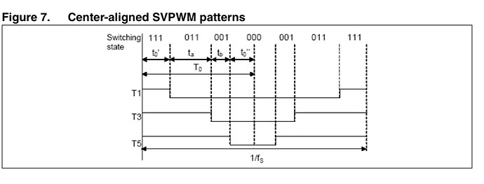
FOC works by determining the sector to understand which two vectors to alternate between and then from this what phases to be high or low in what order. The time for switching is determined by calculating t0, ta and tb.

The way I would handle this with a single timer is the following.

Set timer TOP value (I.e value at which timer rolls over) to pwm period based on the prescaler and frequency.

Timers then usually have two compare values (CompA and CompB with Arduino Timers).
Depending on how you want your pwm strategy (centre aligned or edge aligned) you would just set the compare values as needed to t0, ta and tb. At each interrupt you would switch which ever of the 6 FETs you need to.
Image to illustrate centre aligned implementation:

Example (using the illustration above which has further split the pwm period in half, I will do the same and just focus on the left hand side)

Pwm period / T0 = 100 clicks and is always the same!

t0 calculated to be 50 clicks. You split this in half to get t0’ and t0” both at 25 clicks
ta calculated at 20 clicks and tb calculated at 30 clicks.

Output pins set for started values.
CompA set to t0’
CompB set to ta

When CompA fires you change your output pins and also set CompA to CompB + tb

When CompB fires you set CompB to CompA + t0”.

This can go on and on within the pwm period.

Yes, unfortunately the reality of this is quite complex.

The library supports 14 different MCU types. Most support a 6-PWM mode, but not all.
Where possible, we try to use the motor control features of the MCU, if available, to implement hardware dead-time insertion.

So while we work on getting this running, we should choose a single MCU type to do first, otherwise it will be a nightmare trying to debug everyone’s different setups while developing the code.
My suggestion would be to use either STM32 or SAMD, as these MCUs have the strongest motor control features coupled with good ADC features. ESP32 would also be nice, but the ADC is a bit crappy.

On both of these MCU types we already support software 6-PWM, which will be easiest to work with as the 6 FETs are already controlled separately in this case.

Note that for both of these MCU types, the pins used will have to be carefully chosen for this to work well - you will want 6 pins on the same timer, but not using the inverted channels on STM32.
These MCUs don’t have a pin mux like some others, so the timers available on a given pin are pre-determined.

That’s more or less what software 6-PWM does, but its not simple, and you can’t just use any timers and hope it will work. High side and low side outputs need to be perfectly aligned, and the different phases need to be aligned as well if low-side sensing is to work. The timings involved are very tight (consider 60kHz PWM with a duty cycle of 1% - that’s only a 166ns pulse! even on a very fast MCU you won’t be able to handle such timings in software only, you’ll need the hardware PWM support to keep everything lined up, trigger the current sensing at the right time, etc)

This will be the smaller problem. We already have 1-PWM mode for some MCU types since the last release, and I will add the others soon.
The break resistor should use a different timer to the motor PWM, then we can set the frequency independently.
@Juan-Antonio_Soren_E is correct that this will exclude the simpler 8bit ATMegas, as they only have 6 PWM outputs in total, but these MCUs would be too weak anyways in my opinion. And a 32bit MCU isn’t necessarily expensive… (e.g. RP2040 and ESP32)

I agree with the direction in general, but still have to think about what a “simple” API for this will be. We also have to consider that this will probably be in development and testing for a little while (esp. until more MCU types get supported), so we need to “protect” the other users of the library from the unfinished code.

For these reasons I suggest the following:

  • we’ll add the building blocks we need in the PWM drivers, this will be in the core library, because it would be very hard to seperate, and because if not used it should not affect anything existing.

  • we’ll create a new “BrakingBLDCMotor” class in the drivers library for now. It can subclass the standard BLDCMotor and override/add new features as needed.

  • once everything is working well, and if Antun agrees as well we can take it over into the main library.

  • improving the current sensing is an ongoing effort in the core library anyways.

  • new CurrentSense and VoltageSense classes for sensing bus (or other) voltages/currents can be added in the drivers library for now.

I don’t actually like the look of that pseudocode in terms of the main loop(). I think something more along the lines of:

BrakingBLDCMotor motor = BrakingBLDCMotor(pinA_h, pinA_l, ..., REGEN_MODE_3PWM);

// init
motor.setRegenVoltageTarget(12.0f); // boost to 12V
motor.setAutoCoast(true); // coast if motor speed exceeds target


// during operation
motor.setTarget(target, max_velocity); // coast if velocity exceeds max

motor.brake(braking_torque); // apply braking torque to actively slow motor

but I have to admit I’m still fairly fuzzy on what the best API will be.

1 Like

Another MCU we could target is the Portenta H7 - Arduino’s “Pro” flagship MCU. We support it at the moment, but support could be much better.
This MCU is amazing - a dual core STM32 M4 / M7, with peripherals like PWM switchable between the two cores, shared memory and more.

But I’m guessing people will be turned off by its $90 price-tag :wink:

1 Like

Thanks @runger !
I was thinking the same thing in terms of targeting one MCU. As it happens I have a Nucleo F446RE at home which is what I plan to use for the development / trials.
As soon as the new BrakingBLDCMotor class is in let me know and I will happily work on it offline to get something working.

Cool! I have one of those as well, and I think Antun maybe does too, so lets target that for development for the moment.

A more difficult question then is which driver hardware to use? Any suggestions?

One possibility could be to use the DRV8316REVM, which I think would work. The DRV8316 is a nice driver, and this EVM board would have both phase (low-side) and VBUS sensing. The reverse polarity protection and input filter can be bypassed.
But maybe its a bit low power (5A / 8A max)?

It’s available for purchase, e.g. at Mouser, although the price of $120 or so might be too high?
In any case, I have one.
If we decide on this one, then I’d probably design an adapter PCB to easily plug it to the Nucleo and accommodate any missing pieces like the brake FET and resistor.

I would go for STM32H750. You can get it for $15, and it’s as powerful as the Arduino Portenta H7, except this is single core. The price difference is quite massive. Also, this is probably the only practical MCU in a reasonable price range that can reliably control two motors and have enough computational power to run extra logic on top of the control loops. It has the same core as the Portenza M7 running at thee same frequency. Which means, with minimal modifications you will make SimpleFOC run on Portenza later if needed.

Having full SimpleFOC support for a modern and powerful MCU is very important.

If anyone is interested I can design and order and ship to whoever is interested a development breakout board for test and development. Just PM me your address. It should not take more than a week, and it’s in stock.

I will, however, trade in this for a SimpleFOC coasting feature :grin:

The Portenza is really expensive. I don’t think too many people will go for it. For the price of 2 Portenza boards I can make 10 development H750 boards.

Cheers,
Valentine

PS I meant 750 not 723, I’m editing the post. The 723 has no Arduino support. No CORDIC either.

What I am waiting for is this
£33.38 29% Off | DRV8302 Motor Drive Module DC 5.5-45V 15A High Power BLDC Brushless PMSM Drive ST FOC Vector Control Amplifier Module

The DRV8302/8301 board. Has 3 low side current sense which can help us work on the stability of this.
BEMF sensing, 3 or 6 pwm input….

Don’t have experience with it as it hasn’t arrived but should be ok to do the job.
I don’t think it is an issue to cover multiple drivers as long as the MCU we use is common.

I wouldn’t rush ahead on that… H723 doesn’t seem to have Arduino support… H750 there are some boards with Arduino support, but apparently no “Generic” board - I think I’d be spending a lot of time coding board and framework support files.
I’ve done it before, so I know I’d like to avoid that if possible.

Also CORDIC features aren’t that useful (already looked into it) as they’re fixed point math while we use floating point. They operate asynchronously to the main MCU, and integrating them would be a major challenge, with unclear benefits

Yeah, we have to be careful there too - this will all incur major delays, and add hardware testing effort etc… and sending boards from US to EU or vice versa will cost $30-$60 per shipment, plus duties. So by the time the boards are ordered and sent around they might not be that much cheaper than the Portenza…

Lets stick to the F446RE for now, that’s a reasonable choice to start with, and the Nucleo can be ordered from e.g. Mouser for EUR 15, its in stock.

I’m more interested in the motor driver we plan to use for this.

Here also I’d advocate choosing a finished product everyone can just order from Digikey/Mouser…

Anyone like the DRV8316REVM ? Any reason it can’t work?

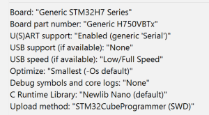
I need some help on this because I can successfully build SimpleFOC without any modifications on generic H750VB

Why would you believe there need to be any board and framework support custom work?

Cheers,
Valentine

I don’t see this driver in stock. Any board that is available?

Cheers,
Valentine

It looks like a good driver choice apart from the price tag and that I have already purchased the other one :pensive:
Is there an issue working with two drivers?

No, not really - just that everyone’s experience debugging it will be different, which will make things a bit harder…

The AliExpress board looks fine too. Maybe I’ll just order one of those…

Funnily enough I ordered it because it was on with fairly high voltage and current rating on the SimpleFOC hardware page. Shipping time isn’t great though

Hmmm… and it also doesn’t do the VBUS sensing, so that would have to be added externally… but lets see if we can make it work, I’ve ordered one too.

Ok, I’ve made a start on the easy stuff.

I’ve added 1-PWM mode to STM32 (it compiles but is as yet untested, because I’m on holiday away from my workbench - no STM32 MCUs or oscilloscopes here to test it :smiley: )

And I’ve made a skeleton BrakingBLDCMotor class in the drivers repository. It doesn’t have any actual functionality, but its the beginning of the API.

SimpleFOC library with modifications needed can be checked out here:
https://github.com/runger1101001/Arduino-FOC/tree/dev
(dev branch, but in my fork of the repo for now)

SimpleFOC Drivers library with the new BrakingBLDCMotor can be found here:
https://github.com/simplefoc/Arduino-FOC-drivers/tree/braking
(it’s on the branch “braking” until something is actually working)

Next building block to tackle will be the extra ADC channels support - this will be a much bigger challenge, requiring API changes in SimpleFOC’s current sense support, and a lot of code modifications for the ADC code.

I’ll get to work on that next, but don’t expect it to arrive quite as quickly :slight_smile:

2 Likes