Not sure I’ve tried on F1. But AFAIK it does not work…
OK I will probably face the same kind of issue with gd32, I will let you know if I find a solution. Could be the adc initializations interfere.
Hi,
I saw this statement in the EFeru wiki:
"
Phase advance/Field weakening can help operate the motor at higher than rated speed, but it also consumes a lot more current as it’s less efficient, and can trigger the overvoltage protection of your BMS when braking.
"
Reading between the lines, it sounds like negative torque vector (used for braking) and phase advance can lead to the boost-voltage we are looking for?
IDK how it could be controlled, just wanted to mention…
Have nice weekend
Olaf
Whoa, lot of stuff in this thread, I’m afraid we might all loose track. At some point a summary should be drawn up and a new thread started with an OP that summarizes the conclusions/poses the most pertinent questions.
One option for some people in some contexts would be to use a battery pack which can be connected in either series or parallel to some degree.
For braking, you would capture the energy, or some of it, but connecting the cells in parallel rather than series, reducing the battery voltage to lower than the output of the motor.
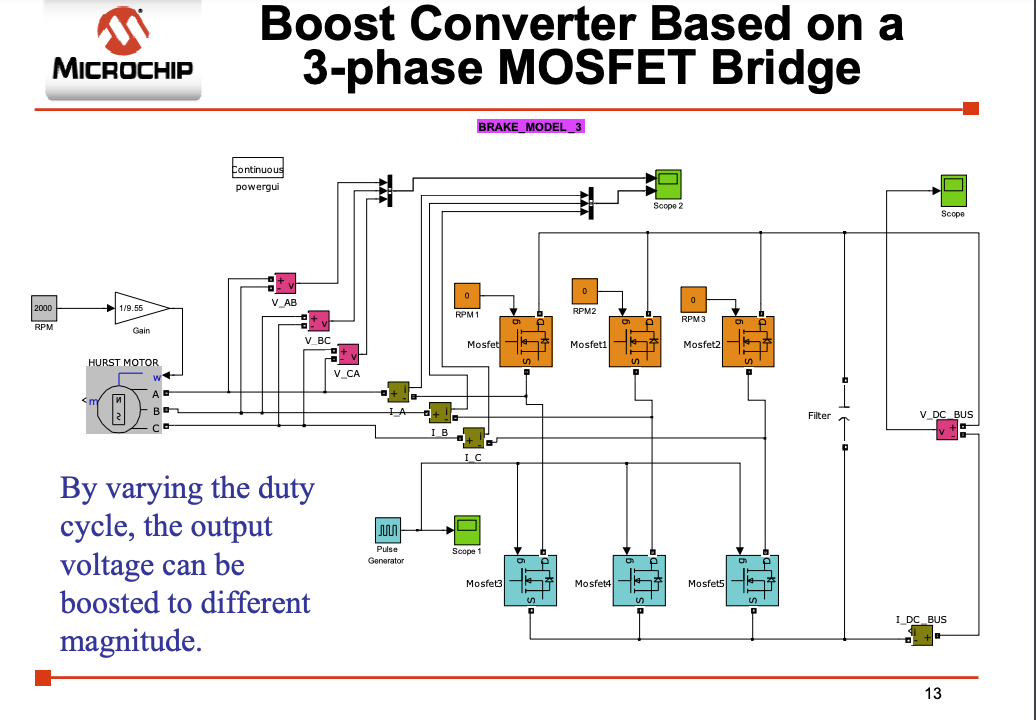
Aside from that I think fundamentally you need a boost converter. What I would probably do is that Simplefoc continues to operate the mosfets that drive the motor in exactly the same way, using the angle sensor. If the driver does this, if the battery voltage is higher than the back voltage produced at the input to the inverter, energy flows from the battery to the motor. If it’s higher, energy flows from the motor to battery. In other words it mimics a brushed dc motor basically. There would be no need to PWM the mosfets in the inverter, you would would use somethign more like 6 step commutation, not sine wave, during braking.
Then you need a dc dc boost converter (buck means step down I think). I think honestly there is probably no way around voltage boosting, energy has to be concentrated on a smaller number of electrons. There has to be an active mechanism to do this, which produces waste heat, or is it the third or second law of thermodynamics that would be violated. Energy can’t be concentrated on a smaller number of particles without an active pumping system, which is never 100 percent efficient. I know that’s a distortion, but I think that is a corrollary that I remember from the fundamentals.
Also the voltage booster would ideally have maximum power point tracking type algorithm because there is an optimum voltage and current draw from the motor that leads to maximal energy return. Draw too much current and a lot of the energy gets dissipated in the motor as heat.
However I think the energy available from all this is very small. Braking is a good idea, there is already active braking by setting torque negative, which you need for a servo motor.
However generators are also useful so basic function to do generator stuff might make sense, if built into SimpleFOC.
Actually I just thought of something, if you measure the back voltage that could be a good way to calibrate the angle sensor too, that’s actually a good idea as it does not get distorted by the loading the way the existing open loop drive approach does.
Maybe measuring the voltage on the output of the inverters is useful, then, for that. Also has applications in sensorless drive.
That’s right, but the MOSFets body diodes already do all the rectifying work for us.
Additionally PWM-ing the MOSFets could lead to a sparkplug-scenario to boost the voltage above battery level. ( several kV from a 12V ignition coil )
A magnetic field in a coil is swiched off and causes a current burst in the opposite direction. The faster you switch, the higher the voltage? Not sure, but the voltage rises until it is high enough to jump over the sparkplug contacts.
IDK if there’s a relation between magnetic fields and the particle/thermodynamics theory, but of course regen braking produces losses (same as the motor, but never both at the same time)
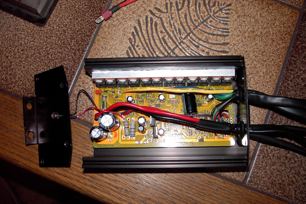
I have an e-Bike controller with regen braking, I could post pictures. Maybe we can identify if there is an extra boost converter or not?
//edit
I found an older pic of it. Not much to see…but a boost converter would need a big coil at least, which I don’t see there:
1 Like
My understanding of what you describe as the sparkplug phenomena is basic induction. I have played with the transformers used to create ignition sparks. They are just transformers.
What happens is that if an inductor has current going through it, then you suddenly halt the current, the voltage will rise, depending on how fast the magnetic field around the inductor collapses, which depends on the core. If it’s air core, that’s the fastest of course, but it also results in a very low inductance for the same number of turns (iron is about 2000 times the permeabilty of air, so a coil with the same number of turns gets 2000 times the inductance).
In a boost converter they use this phenomena, watching the voltage rise and connecting the inductor to a capacitor at the right moment, as others have described here. It is still an active pumping method.
You could try to do this with the motor coils, but you need current to be flowing in the desired direction to begin with. Which is the reverse of what you have during normal drive. Also I’m not clear on how well it would work, you can only transform the energy that is stored in the inductor. This would entail forfeiting energy harvest from the rotor while you did this.
I think, we are on the right path:
I found an article on wikipedia about a flyback transformer, which is basically an ignition coil but is used in SMPSs.
Or check out the Joule-thief circuit
It works with identical primary and secondary windings, but still boosts the voltage in a very simple way.
Somewhere between the lines is the answer how to use this for a BLDC booster.
")
2 Likes
Nice video.
When he talked about that the BEMF is always lower than the supply voltage I thought “not another YT video spreading lies”.
Simplifying the equations by replacing inductivity with resistance!? That actually raised my blood pressure…
But when he showed the PWM side of regen braking, it made sense.
Current must flow
He doesn’t say how the current is suddenly able to flow into the battery, but that’s the part I have described as the sparkplug-miracle.
Questions are,
can we estimate or measure the best PWM required for optimal regen?
Are the DRV83xx drivers able to switch that way?
I will reply here to your question in the Lishui/Ebics thread so we stop being off topic there ![]()
This code is simple.
If the torque is in same direction as the motors movement, you are in motor mode, otherwise you are in generation mode.
If you exceed the battery current in motor mode or exceed the regen current in generation mode, you need to limit the current.
SimpleFOC can already control the Q axis current, it just needs to be able to limit the battery regen current.
I think in some use cases you might also want to limit the voltage, like when using field weakening, because the generated voltage will be higher than BEMF, and can be too high for the battery I guess.
1 Like
")
4 Likes
I’ve learned:
- BackEMF will not charge your battery
- Frequently shortcutting a freewheeling motor will cause voltage spikes (boost converter)
But what he did in the end of the video was using a break resistor (ODrive-style?)
There is still no regen, right?
I wonder, if we can provoke shoot-through to boost the voltage?
Like, reducing the dead-time of a 6PWM driver until we frequently shortcut the motor/generator
Regen can kill the PSU.
I am using an Ideal Diode to protect my PSU, but based on a discussion with him, It protects the PSU but can kill the controller.
So that energy has to go somewhere, that’s the idea behind the brake resistor.
He shared a link that has good explanations.
I am convinced we already do regenerative braking with FOC and SVPWM, we just lack a way to limit the regeneration.
No, this would be bad… guaranteed death of your driver. That’s not what is happening in the video - at no point are the high and low gates shorted. What’s shorted is the motor, across all the low-side (or high-side) FETs.
You can already regenerate if you just commutate the motor slower than its actually going, or in the reverse direction. And if you have a battery connected instead of a PSU, then the battery will charge.
The problem is the voltage spikes caused by sudden changes in current - at the moment there is no way in SimpleFOC to measure and control this. To have effective regeneration you would have to be able to measure and limit the voltage, so that you don’t cause damage to the components with too high voltages… one way to do this is with the active shunt circuit as suggested in the video.
You are right, I mis-interpreted the diagram where he showed the charge current path going through D1 and D2.
I watched the video again and he PWMs the low-side switch to boost the voltage.
Isn’t there a way to calculate the voltage rise instead of measure it?
I’m sure it’s controllable with the low-side PWM duty cycle in relation to RPM of the generator.
Like telling the motor to spin at half the speed it actually does ( or any other fraction of actual speed)
Doing regen braking should be easy, you simply command the Q current to be negative (or in the direction which produces torque to slow down the motor). This is assuming you are using FOC current mode and not any other mode provided by the SimpleFOC library.
Then you will need to know the maximum current which the battery can be charged with, also taking into account other motors connected to the same battery, and set a current limit for the negative input current.
To estimate the input current no additional current sense hardware is needed, you just multiply each phases duty cycle by the phase current, do this for all three phases and add them up. In my experience this method for measuring the input current is quite accurate and is usually within 20% of what the current clamp shows. Here is a simplified version of my code which achieves this:
inputcurrent = (htim1.Instance->CCR1 * PH1_current + htim1.Instance->CCR2 * PH2_current + htim1.Instance->CCR3 * PH3_current) / 1000;
Where htim1.Instance->CCRx are the PWM duty cycles of each phase between 0 and 1000, PHx_current is a variable which contains the phase current, and inputcurrent is the input current.
I believe the accuracy of this method can be improved significantly by compensating for the dead time of the driver, but I have not tried it yet.
If you have only one motor, you can estimate the input voltage rise by adding up the ESR of the batteries and the resistance of the power cables. However this method will be very inaccurate, and won’t help at all with overcharging the batteries. A better way to do it would be to have a resistor divider which feeds the input voltage into an ADC.
If either the voltage or the current limit is exceeded in regen mode, the software should reduce the Q current, so that the regeneration is reduced to prevent damage to the batteries.
A simple way of measuring the voltage and current would be to use a microcontroller with at least 4 ADCs, such as the STM32G474, so the ADCs are independent and the voltage measurement won’t interfere with the current measurements.
It is also possible with microcontrollers with 2 ADCs, such as the STM32G431. You can use the Injected Conversion Mode of the ADCs to measure two of the currents for FOC, and then use the regular conversion mode to measure the voltage and any other analog signal which is not that time sensitive. But doing this needs a lot more programming work. When I was programming the STM32G431 with Injected Conversion Mode, I encountered an issue. When I used the HAL library to set the channels, the conversion result would be off by around 150 (0.12V). But when I wrote the ADC registers directly to set the channels the conversion result was correct again.
Hope this helps.
1 Like
You say it’s easy, but at the same time you suggest adding a second MCU (or use a specific MCU with more ADCs)?
My open loop version would work on any MCU and it wouldn’t cost precious MCU time.
Sure it doesn’t include dumping energy at full battery, but it’s a starting point.
Because of how slow HAL library is? Or there is some issue with the HAL that intrinsically does not set ADC conversions up correctly? I would like to hear more on this.
I believe that either I was not using the HAL library correctly, or there is some issue with the HAL that intrinsically does not set the ADC correctly. The FOC and current sense code was still running at 50KHz just fine when using the HAL. It only happened with some of the ADC channels, and it only affected the injected conversion channels and the regular channels were reading correctly. I haven’t investigated this further since I switched to writing the ADC registers directly.