Recommendations for a 2 axis camera stabilization system

I am starting my first attempt at creating a stabilized camera system using gimbal motors instead of the servos, step or DC motors which I am more familiar with and it is pretty intimidating.

The requirement is to correct the attitude of a 1kg DSLR camera for drift(=yaw) and roll. Only 2 axes. The cameras go into a pod which is attached to the wing strut of various light aircraft. The gimbal assembly has to fit inside the 230mm diameter pod tube so space is limited. As a result the loads will not be perfectly balanced. If balance was critical it would be possible to add counter weights but I would prefer to avoid that if possible. An illustration of the layout is attached. Please note that the motor sizes that are shown (60mm diameter and 46mm high) are a complete guess.

3D4

I have no idea of what size of motor might be suitable for this sort of load.

As far as the controller is concerned, we have reasonably high end IMU’s in the pod so I can generate the angles I want the motors to go to. How to translate that angle to an actionable movement on the motor is a big, big confused blank for me. Incidentally the maximum range of movement on both axes would not exceed more than 45 degrees from center. There is 24v power available although something less than that would be desirable. I would really like a solution that is as close to plug and play as possible.
.
Can anyone help me with some advice please? A shopping list perhaps? I know we won’t get it right first time but an educated guess would be way better than the complete shot in the dart that I will have to make.

Hi @Kusana , welcome to SimpleFOC!

This sounds like a nice project! If you search in our forums for “gimbal” or “3-axis” you will find some other projects in this direction, you may find them useful.

We’ll get you sorted out :slight_smile: no worries!

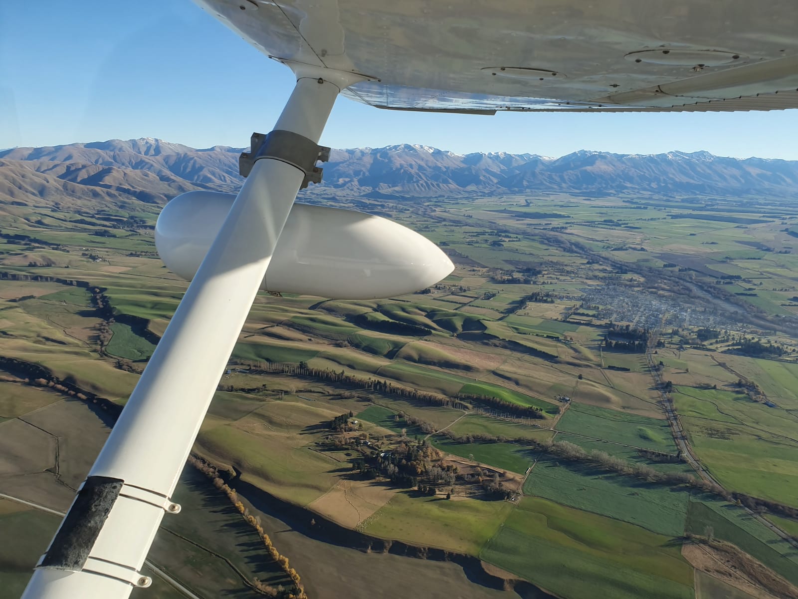
Do I understand correctly from this that the gimbal and camera are shielded from the air resistance forces by the pod? So the gimbal doesn’t have to hold the camera in place against the passing air during flight?

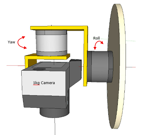
I think balance is very important, otherwise the motor will be continuously “lifting” the camera to hold it in place - this will make the gimbal use far more power, with accompanying heat generation problems.
It will also be subject to “uneven” forces as it rotates if the camera is not balanced, which won’t make control easier.

This will require a few iterations and lots of testing to get to the final version… to start with, just put each motor in angle mode, and use the IMUs to command the angle to the motor.
(To be clear, don’t actually start in angle mode - get each motor running and well-tuned individually first by following our documentation and checking the modes starting with the simplest (torque-voltage) and proceding through them until you get to the angle mode. Then once each motor is working individually, put them together into the gimbal system and start on your outer control layers).
So angle mode directly controlled by the IMU as the initial gimbal control code, and from there we can look into more complex control loops, filters and other ideas to improve performance.

In this design the motors are “carrying” the full weight of the camera (and even a lot more for the first motor), regardless of whether it is balanced for the rotation or not.
Personally I would design it in a way where the weight is carried by structural parts and bearings, and the motors are only driving the gimbal in its bearings.
In this design the motors (especially the first one) are subject to very unfortunate shearing forces which will affect the performance and control (I am making assumptions here)

If you only need 45deg rotation in either direction on 2 axes, this makes your life much easier! You don’t even necessarily need to use the motor hollow shafts in this situation.

I would order 2-3 different sizes of gimbal motors. The iPower series gimbal motors from iFlight RC seem suitable, also the gimbal motors from emax or T-Motor. I would order ones sized 5010 and upwards for a 1kg camera, but you could also set up some physics equations and work out the required torque :slight_smile: some of the vendors might help you out by giving the maximum camera weight the motor can deal with - that will be an optimistic-approximate value on the one hand, and would certainly assume the camera is well balanced on the other hand.

I would order magnetic sensor evaluation kits like the AS5047P - these little PCBs aren’t too expensive, come with the right magnet and are fairly easy to interface via SPI or ABZ. You will need one per motor.

I would order some STM32 Nucleo boards. Nucleo-64 boards are a bit bulky but don’t cost much and the G431 or G474 boards are excellent for motor control.
Alternatively you can also use various boards from Arduino (the Nano ESP32 might be nice), from Adafruit or Sparkfun, as well as many others. Keep in mind you will need quite a few pins for motor driver and sensor, and a way for all the boards to communicate.

Can you run 2 motors on one MCU? Yes, but it’s not ideal as you will only have half the MCU power for each motor, and the code is much more complicated to set up. But if you want to go this route then definately choose a fast STM32 MCU, or an ESP32.

Finally the driver boards - the SimpleFOC shield or SimpleFOC mini generally have enough power for gimbal applications, but if you need more, perhaps the newly introduced SimpleFOC driveshield would be suitable for your needs?

Are you intending to make PCBs for it in the end, or assemble it from stock components?

Wow! That is quite a response. Thank you very much indeed.

Answering your questions and comments on your advice :-

Yes, it is fully shielded from the airflow.

I hear what you say about balance. Weight, within reason, is not an issue so I can add counter weights to at least largely deal with that. There is not much that I can do about the basic layout because of other limitations.

I am conscious of the roll motor being subject to shearing force and could devise an H frame that attaches to the backing plate to provide support on the opposite side as well. It would just squeeze in. However it would greatly complicate the structure and I think it might be worth trying without it first. From what I have seen the bearings in those motors are pretty robust things. There are also quite a few commercial open frame gimbals which are claimed to be suitable for much heavier cameras and appear to have shear arms considerably longer than the 65mm in this design. I guess that a preliminary bench test will quickly reveal all.

Yes, I was thinking along the lines of perhaps a 5225 motor or equivalent. Quite a few motors in their specs say “suitable for cameras of X weight” but exactly what that means is hard to say. Something that promises a stall torque of 2Nm might handle it?

Making a dedicated PCB for it is out of the question. It has to be stock components but the fewer and smaller there are of them the better. Would it not make sense therefore to get a motor that has both the driver board and the magnetic encoder built in or on? Like this perhaps (Tinymovr Servo Kit R5.2 NEMA)

I was wondering about one or two MCU’s and you have settled that. They just need to be quite small if there are going to be two. Nano size if possible.

Anyway, thanks again. A big help.

On top of the mechanical and electronic issues discussed above, you’ll also need to consider those points:

  • IMU Calibration: not sure how familiar you are with this, but this is a critical point if you want to achieve a correct stabilization. As you system will have to deal with wide temperature changes, your calibration needs to be “temperature-aware”, which is no easy task.

  • Motor Tuning: unless you use sliprings everywhere, a camera gimbal cannot be rotated freely at 360°, because of the wires. This makes tuning the motors (i.e. finding the PID control parameters) under load difficult.

  • Stabilization Logic: the math involved here is quite dense, and, AFAIK, source code is not publicly available. Familiarity with the geometric transformations used in 3D graphics is not enough: you are dealing here with a mechanical system based on angles, so you’ll need Euler angles. That’s a whole field in itself.

  • Control: in case you want to send commands to your gimbal (if only to manually correct your yaw every now and then because of the drift), you’ll need a communication API of some sort. This is not very difficult, but it adds up.

So, if this is a hobby project, it’s a fantastic opportunity to learn about various fields. But if your goal is to achieve a usable solution, you might want to consider off-the-shelf gimbal controllers (such as BaseCam and similar).

IMU calibration and handling the outputs in a 3D environment I can deal with. Euler angles (I prefer using quarternions), Kalman or similar filtering, smoothing algorithms, spherical and projected coordinate systems are all home ground.

Motor tuning and motor communication are not.

Trying to cover all bases, I put out an inquiry to Basecam several days ago and then a reminder. So far no response which does not fill me with encouragement about going that route.

I think the specs of this kind are a good indication, but as mentioned I think the assumption is always that the gimbal is balanced…

This depends greatly on your physical setup and how you want to run which cables. An all in one driver would probably simplify things in terms of hardware and cables.

Tinymovr looks like a great project, but it uses a fairly rare integrated MCU/driver which we don’t support. But of course you can use its stock firmware.

The Moteus controller is somewhat larger but has integrated sensor and more power.

BaseCam seems to respond only to paying customers. Despite this, they offer good products and responsive support.