Hello everyone!
Recently I got the Simple FOC working with an Arduino Nano and a third party motor driver board, (pretty happy with the result!) Then I started looking into building a multi-joint robot with it, before which I need to figure out what could be a proper option for communicating between a Raspberry Pi and multiple Arduinos. Ideally it would be:
- Able to send commands from Raspberry pi to all Arduino (motors) and receive feedbacks
- Easy to wire up
- The communication not adding too much computation overhead (so hopefully not disturb the SFOC functioning on the Arduino Nano since it is not powerful)
- Relatively stable connection (10 to 20cm in terms of data transmitting length, nothing crazy)
- For frequency, anything higher than 100hz would be “usable” based on my past experiences when making robot dogs and stuff, and obviously the higher the better
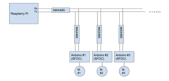
I did some search online and figured that I may want to use RS485 and Modbus, and the overall structure would be something like this drawing below. I wonder how feasible this would be in terms of performances and if there is any better or easier solutions. Thanks in advance!
1 Like
Hi @Lethic_Z
There is at least one interesting option in case your MCU supports CAN bus protocol. Then you have to develop a CANOpen-style application protocol to control and monitor your SimpleFOC devices over a CAN network to send commands and receive information.
Hi
Take a look at this;
Would love to se a can fd ECU/mainframe for a custom 4WD/3WD EV
RPi is a USB hub. Arduino Nano is a USB device on the hub. As long as your nanos don’t have to communicate among themselves in a canbus configuration, but you need a single master rpi and all nanos are strictly slaves your cheapest and easiest codewise to work with (bidirectional star configuration) would be to use an off-shelf multi-output usb hub. Say your arm is 6 degrees of freedom, base rotator, shoulder, elbow/ulna, ulna rotator (wrist cuff rotator), and two for a reasonably simple gripper , and you need a reasonably simple usb hub. Then use simple serial for communication at 152000baud and bob’s your uncle. You may have a bit of a tizzy hard-naming and calling the usb devices on the hub but i’ll leave this for you to figure out, not a biggie. I’ve done it in Java on pi talking via serial to a dozen nano in arduino ide, not sure what’s your language of choice.
Hi @JorgeMaker Thanks for the suggestion! I will definitely look into using CAN. The communications speed of CAN is not super fast but should suffice my applications.
1 Like
Thanks @Juan-Antonio_Soren_E This CAN FD Expansion HAT looks great for Raspberry Pi, I may get one of it I go with using CAN for this!
@Valentine Thanks! That’s an interesting and sounds pretty straight-forward! I should be able to use udev rules to sort out the namings of the Arduinos. I will probably use Python or C++, and this seems to be doable for a robotic arm application, it might be trickier to get it work on a running and jumping robot dog with USB cables.
Running and jumping requires real-time centralized processing. Using rpi to arduino to yet another mcu (your 3-rd party foc controller) and then receiving back and processing real-time position of each degree of freedom will introduce a lag that you’ll have hard time fighting. You’ll end up solving a really complex delay differential problem of mechanical impedance instead of your jumping algorithm. Unless your dog does relatively simple pre-programmed tricks, and you pre-program your physics and your dog is not autonomous you may want to rethink using nanos and rpi and python. Best rpi has only four cores, and python is and interpretive script, not a real language. Your solution needs to multi-thread each nano so you need a lot of processing power. Also depending on your dog weight, the dynamic load on the bldc must be somewhere in the 10 to 100Nm. That’s 1 to 10 kilos*meter. You may get it to walk and may be slow trot real time if you optimize the physics but jumping and flipping may be a bit to much. Use NUCLEO-H755ZI-Q board directly communicating with each of the the bldc controllers and doing the real-time processing and communicate with the rpi for user interaction. Ditch the nanos, you will save a lot of lag and you won’t need any protocol, just run power wires to the motors. Analog rules real-time. The nucleo will control directly the BLDC controllers and also has tons of input/output pins (144), built in ethernet, arduino compatible, etc.
Of course, i may be assuming to much, so you can ignore my suggestion.
Edit: Upon reading the original post it seems the Arduino Nano itself is running foc and pwm to third party motor driver board? I mean the nano is the foc mcu itself? In that case let me think a bit.
Use rpi only for user space. You need a dedicated real-time command and control – nucleo.
Option 1. TX/RX with a 144 nucleo in a star config. Simple serial, simple coding, two wires, nucleo can support up to 8 simultaneous serials, bundle together the nano+drivers on a protoboard and connect to the nucleo. The length of the wires is negligible. Then run only power wires to the legs.
Option 2. Use PWM to talk to the nano, since you only need a single vector control, which is angle. Then you need only one wire to each nano. The nucleo has about 20 pwm pins, and use the rest to receive telemetry from the nano (i assume angle so the nano will communicate directly the angle to the nucleo via PWM). Thus, you cut the comm to 2pwm to/from the nano, no comm protocol, 0 lag, analogue, limited to only how fast the nano can beam back your gpio data from the loop().
Option 3. CAN bus. You will need a can shield to the nano. You will need https://www.seeedstudio.com/Serial-CAN-BUS-Module-based-on-MCP2551-and-MCP2515.html. Then hook up the nucleo to the can bus. This is probably the most complex and expensive. You will need a separate canbus shield for each nano.
Connect the rpi to the nucleo using simple usb. If you want super high speed, use ethernet. But do not use the rpi for the critical real time work. In a way, the nucleo is your medulla oblongata and your rpi is your cerebellum. You can offload any time critical work or default behavior to the small brain and use the big one for the high level control.
Hi Valentine,
I agree that the CAN solution is the most expensive compared to a simple Serial connection, but from a future EV dev point of view, the HDMI/HMI on the pi is a huge plus. Yes it is a different scenario. If the nano´s had a onboard CAN transceiver , it would be a easy choice. I will nonetheless arque, that the CAN solution is more rugged and more immune to stray EMI. @Lethic_Z if you have the time and resources, explode the nano design and merge it with a custom BLDC solution with a onboard CAN FD IC.
The can shield already has an atmega328p so the end solution will be stringing up one nano talking to another talking to the canbus controller talking to the bldc driver. The lowest total cost of the nano with the shield is $20. @Lethic_Z may be better off using a single high powered board with built-in canbus to run the bldc controller because the nano running the bldc foc will also be running the canbus library with whatever other custom code @Lethic_Z wrote on top. One option is leonardo-canbus – HobbyTronics or just get a teensy which is a monster performance and has built-in can and you can run really complex custom code directly on top of the foc and canbus libraries for $20. Teensy’s footprint is also nearly 1:1 with the nano.
@Lethic_Z
Could you please share the 3-rd party bldc controller and motor you paired with if possible? This may help the conversation.
Cheers!
Yeah, here’s the board that I got GitHub - ChenDMLSY/ZM_Xdrive_1.0: 该驱动板支持:霍尔无刷驱动、感应电动势无刷驱动、simpleFOC、直流减速电机改舵机,多样性功能,性价比高. Most of the stuff here is written in Chinese but it’s got a circuit diagram to look at ZM_Xdrive_1.0/ZM_Xdrive_V1.0原理图.pdf at main · ChenDMLSY/ZM_Xdrive_1.0 · GitHub And Interestingly, besides SimpleFOC, it also supports the option 2 (using PWM) you talked above. Basically turning the whole thing into a pwm servo motor.
Leonardo can board seems to be pretty neat! I have always being wondering if there’s low cost Arduino that comes with more advanced communications module on it such as CAN or RS485
@Lethic_Z,
I understand now why you need Nano. If you go with CAN, at that point you could either use a can bus shield between the nano and whatever controls it or redesign the driver board to take Teensy which has canbus natively and draw the canbus leads out to the board to solder a connector.
Question, had a quick look, I see three boards there,two have current shunt resistors but the one you linked doesn’t, or may be they are on the back? Did you try foc with current sensing? May be the answer is in the schematics, didn’t look there.
Cheers!
Edit: Saw the schematics, you pull current sense from the bridges, never mind.
@Lethic_Z be careful with the built-in PWM it may be only analogue and only forward and not RC-type PWM allowing forward/reverse. Also it may be only continous rotation and not a target seeking angle rotation. I don’t see much documentation there (none at all in fact) and the little Chinese description there is Greek to me.
@Lethic_Z
I had some downtime and had a look at the schematics. You could attach a canbus directly to the nano running the foc but you’ll need some soldering and also will sacrifice the serial and will have to disconnect the canbus each time you reprogram the nano. Or you can program the nano outside and pop it in / out in-between. I have no idea what that would to to the timing of the loop or your other custom code overhead. D12 and D13 are available, as well as the d0 and d1 which means you need to bit-bang the mosi. I don’t know, that 's probably a butchering job.
Edit: Yes probably a no go, whoever designed the board killed the SPI by using the MOSI pin but weirdly left the free digital ones blank. Could have done a lot better and leave the SPI available.
If I where to design a very small outline heavy duty CAN FD empowered robot dog muscle, I would take a look a this: https://www.mouser.dk/datasheet/2/268/SAM_C20_C21_Family_Data_Sheet_60001479G-2303053.pdf
I don’t know if there is Arduino support, and the VGFN32 is sold out. There is lot´s in stock of the WLCSP-56, but then you will have to do via´s in pads.
quote:“Yes it is supported on the Arduino IDE, I use the core from mattairtech.
samc code and samd code is very similar , the sand is used in the zero, mkr etc” source: SAMC21 official suport? - Speeduino
How many amps/watt do you intend for the controller to handle?
Let´s flow with this… Use 0402 caps and a minimalistic approach
By minimalistic i mean eg. external centralized power for the processors. Use the capabilities of the processor for dead time insertion (requires register coding). Use the 5v power for switching of gates. Minimalistic. Or put a small LDO on the board and use eg. 12v for switching (less On resistance).
At what voltage do you intend the thing to run?
Thanks man, yeah it looks like the SPI is gone, so the CAN would be a no go for now.
Maybe software SPI can work? (probably too much overhead) I most likely would try out rs475 as I happen to have a few MAX485 carrier boards lying around
Oh, so now you are just ignoring me, how ruud.