Hi!
I am sorry that I was not able to use English well.
Thanks for the wonderful board!
I was just lamenting that the B-G431-ESC1 couldn’t use SPI communication.
I ordered five and they arrived last week.
I confirmed that I can control LED_Blink and OpenLoop using the information in this thread!
I want to do is torque control. I tried to run the code that was working with B-G431-ESC1, but the motor vibrates when it should be stationary, making a strange noise and randomly rotating a little at a time.
Regarding current sensing, I set it as follows, referring to the Power Shield-D thread. (Because it is the same current sensor)
InlineCurrentSense current_sense = InlineCurrentSense(0.055, 1.0, A0, A1, A2);
Would you help me?
What should I be suspicious of first?
Thanks.
This is all the code.
Summary
#include <SimpleFOC.h>
BLDCMotor motor = BLDCMotor(7);
BLDCDriver6PWM driver = BLDCDriver6PWM(PA8, PB13, PA9, PB14, PA10, PB15);
InlineCurrentSense currentSense = InlineCurrentSense(0.055f, 1.0f, PA0, PA1, PA2);
Encoder encoder = Encoder(PA3, PA4, 1000, PA5);
void doA() { encoder.handleA(); }
void doB() { encoder.handleB(); }
void doIndex() { encoder.handleIndex(); }
Commander command = Commander(Serial);
void doTarget(char* cmd) { command.motion(&motor, cmd); }
void setup() {
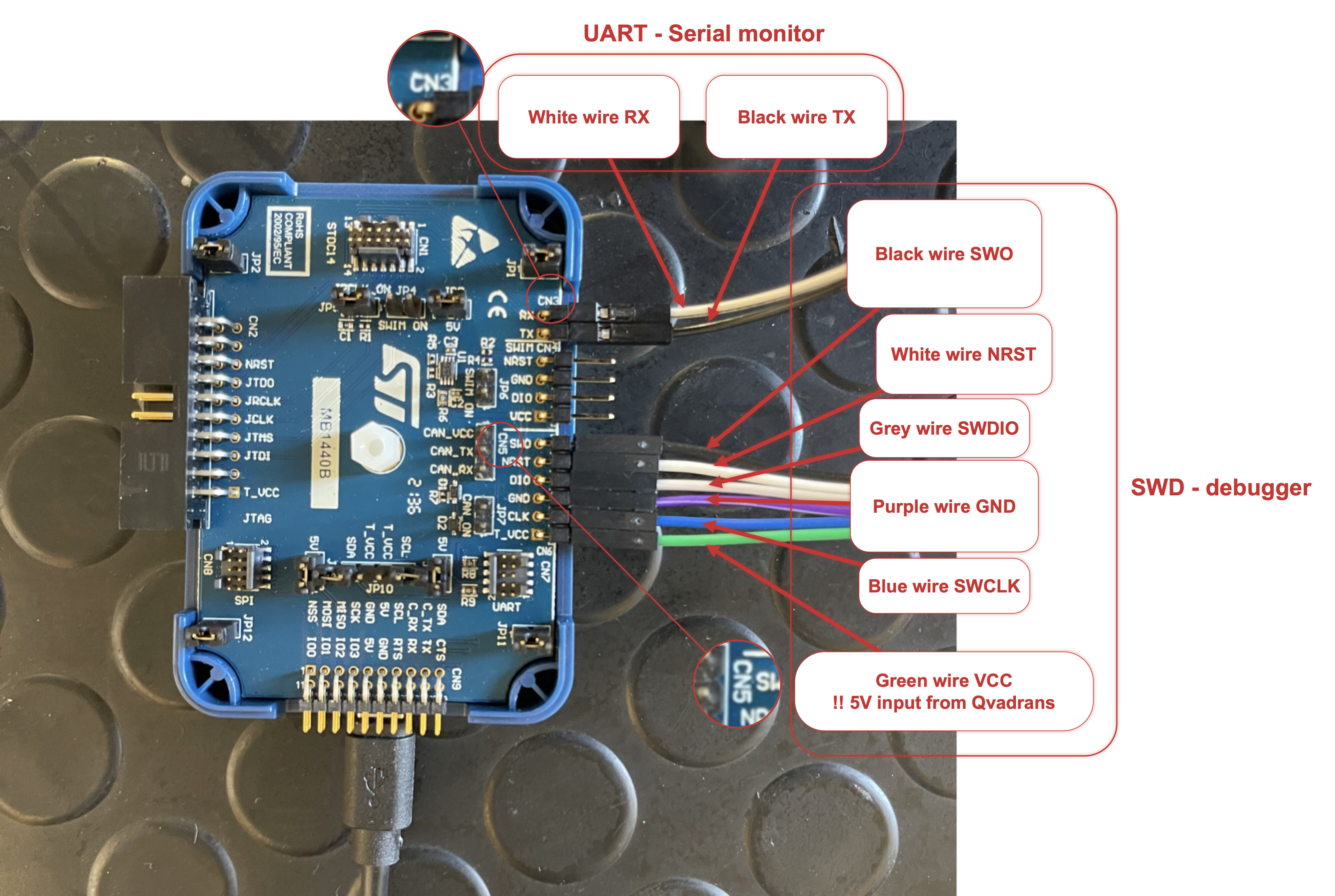
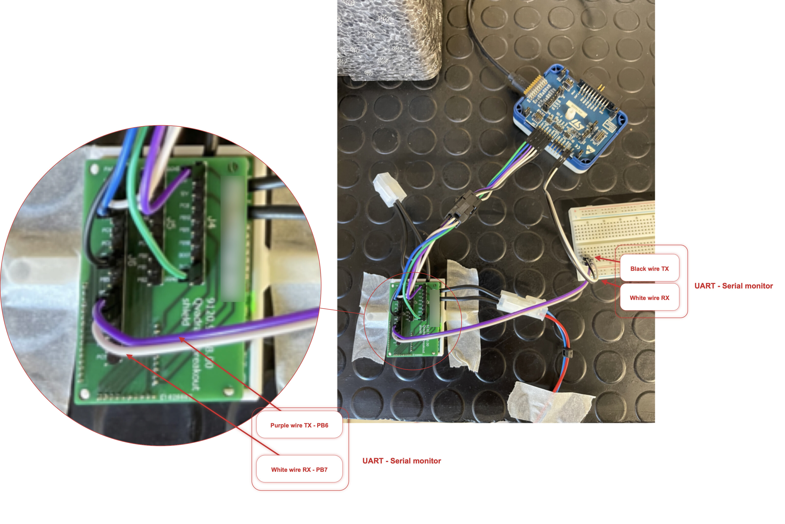
Serial.setRx(PB7);
Serial.setTx(PB6);
Serial.begin(115200);
encoder.init();
encoder.enableInterrupts(doA, doB, doIndex);
motor.linkSensor(&encoder);
driver.voltage_power_supply = 12;
driver.init();
motor.linkDriver(&driver);
currentSense.linkDriver(&driver);
currentSense.init();
currentSense.skip_align = true;
motor.linkCurrentSense(¤tSense);
motor.voltage_sensor_align = 1;
motor.velocity_index_search = 3;
motor.voltage_limit = 7;
motor.velocity_limit = 1000;
motor.controller = MotionControlType::velocity;
motor.torque_controller = TorqueControlType::foc_current;
motor.PID_current_q.P = motor.PID_current_d.P = 0.1;
motor.PID_current_q.I = motor.PID_current_d.I = 10;
motor.PID_velocity.P = 0.5;
motor.PID_velocity.I = 1;
motor.PID_velocity.output_ramp = 1000;
motor.LPF_velocity.Tf = 0.01;
motor.P_angle.P = 20;
motor.useMonitoring(Serial);
motor.init();
motor.initFOC();
command.add(‘T’, doTarget, “target angle”);
Serial.println(F(“Motor ready.”));
Serial.println(F(“Set the target angle using serial terminal:”));
_delay(1000);
}
void loop() {
motor.move();
motor.loopFOC();
command.run();
}