Hello, I am new to BLDC Gimbal Motors and would be very appreciative if anyone can answer one or more of my questions.
I often see gimbal motor performance in grams, do they mean Newton-Meters, weight is not a torque measurement?
Why is the resistance higher in a gimbal motor, since torque is generally proportional to current, wouldn’t it make sense to have lower resistance so you can push more amps?
How do I calculate torque of gimbal motor at stand still?
Can you gear a gimbal motor down and have it spin rather than hold position and it won’t overheat?
I know that’s a lot of questions, but I’m new to Gimbal Motors So Any Help Much appreciated.
I’ll try to answer as best I can, others may be able to fill in more details:
I think they’re just being imprecise. I’m really not to sure what they mean, perhaps gram-cm?
Gimbal motors are designed to hold a position. You can’t push many amps through a motor on a continuous basis, it will overheat (well, depending on design and size, but I’ve never seen a liquid-cooled gimbal).
For practical purposes, you will have to measure it, since it will be affected by so many factors. And unless you have access to an expensive torque transducer, you’ll have to approximate by using a kitchen scale, load cell or similar setup. For theoretical purposes, someone else can answer much better than I.
Yes, they are easy to work with due to the higher resistance. Many integrated quasi-direct-drive motor systems are basically like gimbals with built-in gear-downs.
Probably grams-cm, which you can convert to newton-meters. Very hard to tell unless you quote the actual motor.
To provide you with high torque at stand-still. Gimbals almost don’t move, they just kind of twitch about a rad. If you have very low resistance, you will immediately burn the coils. And no, the gimbals cannot be compared with low ohm high speed motors. The regime is very different. Also gimbals draw very low current, anything over 5A is probably either a gigantic gimbal or not a gimbal motor. While, the low ohm motors easily draw 50A and devlop the power at very high speed.
Regarding the torque calculation, there are some formulas that approach the value but in my experience, it’s a good way to compare motors but not really an accurate number. Here I’ve written the formula out that I use and is most common (I think)
Basically, it proportional to current and inversely proportional to the Kv rating wich is the RPM/V rating that is sometimes not even provided with gimbal motors and actually isnt even a constant.
Also, for gimbals, you can estimate the Kv from the thickness of the copper wires and number poles and windings per pole. The gimbals don’t give kV, they give copper wire and windings.
Wow, thanks for all your answers and also so fast! That torque formula is especially useful. To answer the use case question the main thing I am working on right now is trying to make a robotic arm for automating tasks in general (maybe 3D print removal? ). Now that I found simpleFOC that’s so much easier to do (before I found you guys I was planning on using an Trinamic IC that managed the FOC, but now I don’t have to go through the cost/hassle of that any more!
Follow up question, are the main ways for compact gear reducers just cycloidal and planetary and maybe spur gear box? Cause If I have to gear reduce my gimbal I obviously want it as compact as possible.
If I may ask @Valentine what type of gearbox did you use on your robot arm?
If you have never done this, you can buy for $300 the MIT Cheetah actuator, but then you need to deal with a completely different set of problems, if you plan to make it to a product. If you do this as a hobby, start with a simple planetary reducer. Also, the planetary is a spur gear reducer. Stay away from anything else unless you got the theoretical and mechanical background, as well as money to fund the r&d.
One last question if you don’t mind, I’m trying to work out how to attach the magnet for the encoder, in your CAD do you just press fit it into the print and that’s fine or do you use some kind of glue.
Really, best of luck with your project. I think a 3D printed robot arm is very achievable with a bit of dedication and patience, but obviously it will be very limited in terms of the weight/forces it can handle compared to its metal counterparts.
Nonetheless, I think it is a very excellent project to take on.
If you’re not familiar with Skyentific’s excellent YouTube channel, you should take a look… https://www.youtube.com/c/Skyentific
→ after watching a few of his videos on how to make robot arm actuators, you’ll have no further questions
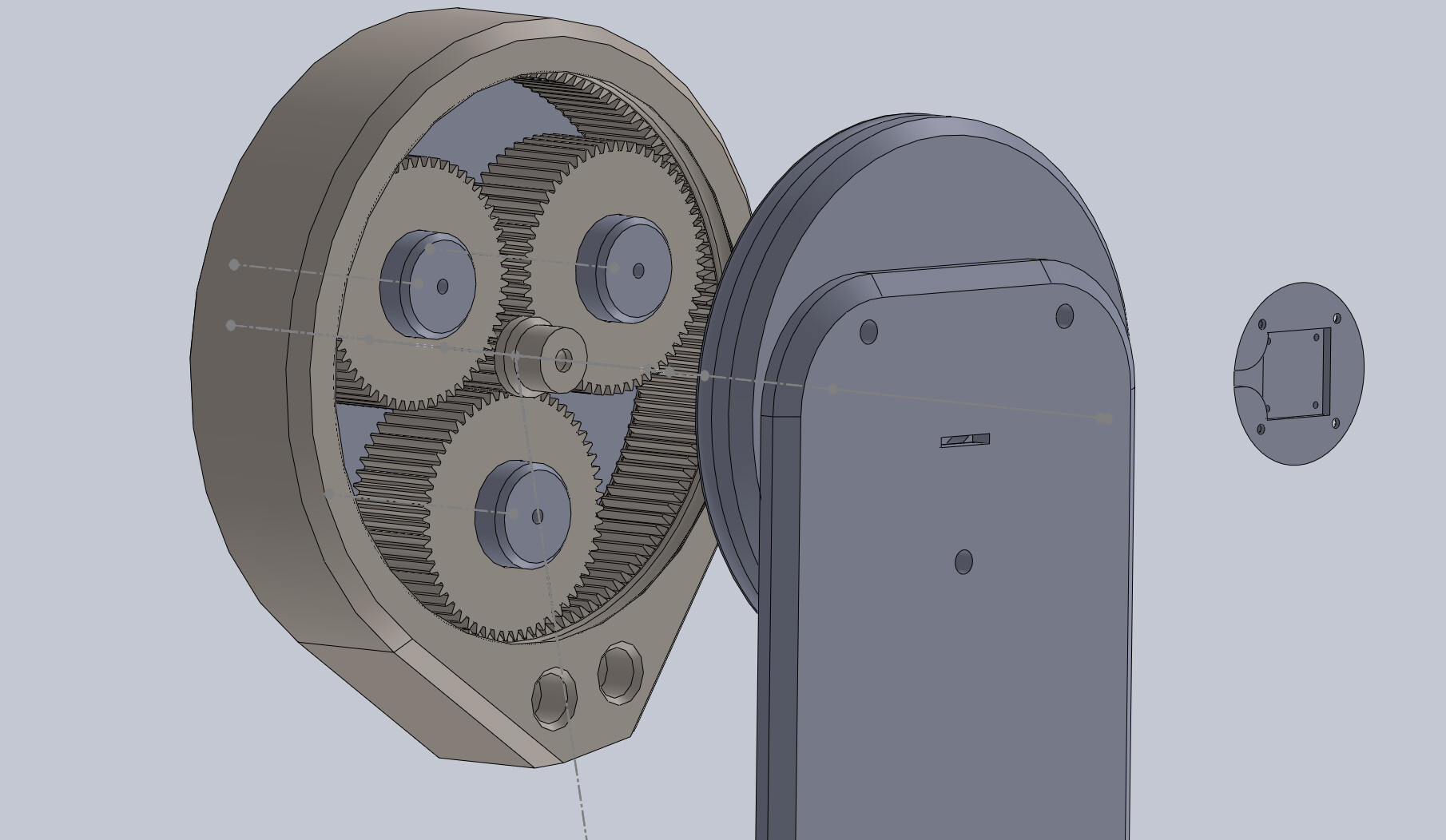
One last thing, the picture I shared is just a conceptual 3D design, not the final design. Real 3D design requires a massive amount of post-production work to make it fabricate-able and manufacturable based on the exact process you will use to make it, down to the calculation of temperature expansion/contraction and moisture absorption tolerances change of where you will run that thing.