hello everyone,
i am trying to control a gimbal brushless, emax gb2808, and i have an optical encoder of Aligent. but i can’t figure out how to use closed loop with it!
the thing is when it starts to align, it says:
"MOT: PP check: fail - estimated pp: 36 "
the number of my ppr on encoder wheel is 100 and in quadrature mode on, i define encoder like this:
Encoder encoder = Encoder(2, 3, 400);
but it doesn’t work!
each time i run the code(simply close and open the serial port), i get different estimations. from 32 to 90, 200 and other numbers!
what should i do? any tips or smth?
P.s: i ran the motor in openloop velocity mode, but it ain’t gonna do the job for me as it’s so coggy!
Your Emax GB2808 has 14 poles or 7 pole-pairs. This motor works very well with SimpleFOC, I have a bunch of them myself and often use it for tests.
However, I am not familiar with your sensor. One thing to note is that the third parameter to Encoder() is the PPR - so in your case I think the correct number is 100.
Generally speaking this could be a bit low, perhaps another user who is more familiar with the encoders can say more on this, but with PPR=100, CPR=400 in quadrature mode, and that’s only just more than one count per 1°…
Most of the other sensors I have seen used with SimpleFOC have a CPR of more like 1000 or more, some of the magnetic sensors are 14bit - so CPR is 16384…
Thanks for the reply. I tried all kinds of numbers in code for ppr
But the estimation always differ.
So you think it’s because of low ppr?
I’m trying to build a balanced motor cycle like Rem-rc in youtube.
I laser cutted plexyglass(pmma) for my reactiob wheel and encoder wheel.
In my country, there’s literally no magnetic encoder, i found one somewhere with smth like 30$ or so, i was hoping that optical encoder would do the job.
Thank you for your answer, really do appreciate it.
I would actually have expected it to work somewhat, even with low PPR. Do you have the chance to check the signals electrically, with an oscilloscope?
Do the encoder outputs need pull-up-resistors? Missing pull-ups is a common problem. Often the sensor works by itself when turning by hand without pull-ups, but then not when driving the motor.
Is your sensor working well when you turn it by hand, with the motor not powered?
Perhaps @Rem666 can comment on the precision required for this kind of project, I haven’t tried it! But my gut feeling is, the more precise the better, for this type of application.
Well i don’t have access to oscilloscope. But i wrote a code to test the encoder. It works
I actually go to angle openloop control
And i count the pulses, it works but the sensor is so sensitive to location. For example in position 1, it counts 90, 92
In position 2 it couns 240, 480
In position 3 it counts 450, 780
I mean just slight changes in encoder position make this big difference
I was thinking about pullup resistors. I’m just not sure if it is the case or not.
And yes it works when working by hand, but it works like i said
Have you been following the encoder documentation here?
If you don’t have pull-ups, you can try if the internal pull-ups make a difference, using
encoder.pullup = Pullup::USE_INTERN;
as described in Step #2.
But often the internal pull-ups are too high resistance, and you need external pull-ups in the range 1kΩ to 5kΩ
Try with the encoder in “standalone” mode, as described in Step #4.
With the encoder in standalone mode and the motor unpowered, the values should change from 0 to 6.28 (the angle in radians) and back to 0 as you turn the motor through a full turn with your hand.
Until this is working well, there is no point in testing any closed loop control modes, it cannot work.
yes i tried internal pull ups. no difference.
i tried standalone example for encoder, it counts. but it’s not consistent, i mean it’s not counting according to the 100 ppr.
but i am certain that the encoder is ok and there is smth wrong with either my code or my setup.
i’ll try external pullups and do some trials. i hope it works.
thanks for the reply
i will provide some documentation of my setup and some pics of my code soon.
i used pullups resistors(3.3 kohm as said in the datasheet, and used it on channel A and Channel B (channel A-> Resistor-> Digital Pin 2 arduino / Channel B ->Resistor->Digital Pin 3 arduino))
same results.
there is one thing i suspect. the motor i bought is not mechanically true. i mean the hollow shaft is all right and turns okay, but the body(which my reaction wheel attaches to) is out of center and not true. could that be the case?
I am not sure what you mean by this… are you saying the motor is an out runner, and the rotor housing does not turn smoothly?
I think for the reaction wheel you will need very smooth operation, if it wobbles on its axis you will make the job of balancing much harder
Could you perhaps provide some more details, including a diagram of the circuit you have now, and the code you’re running to test the encoder?
yes it wobbles unfortunately!
i will record a video of what i mean and upload it soon.
the code right now is just the encoder_example.
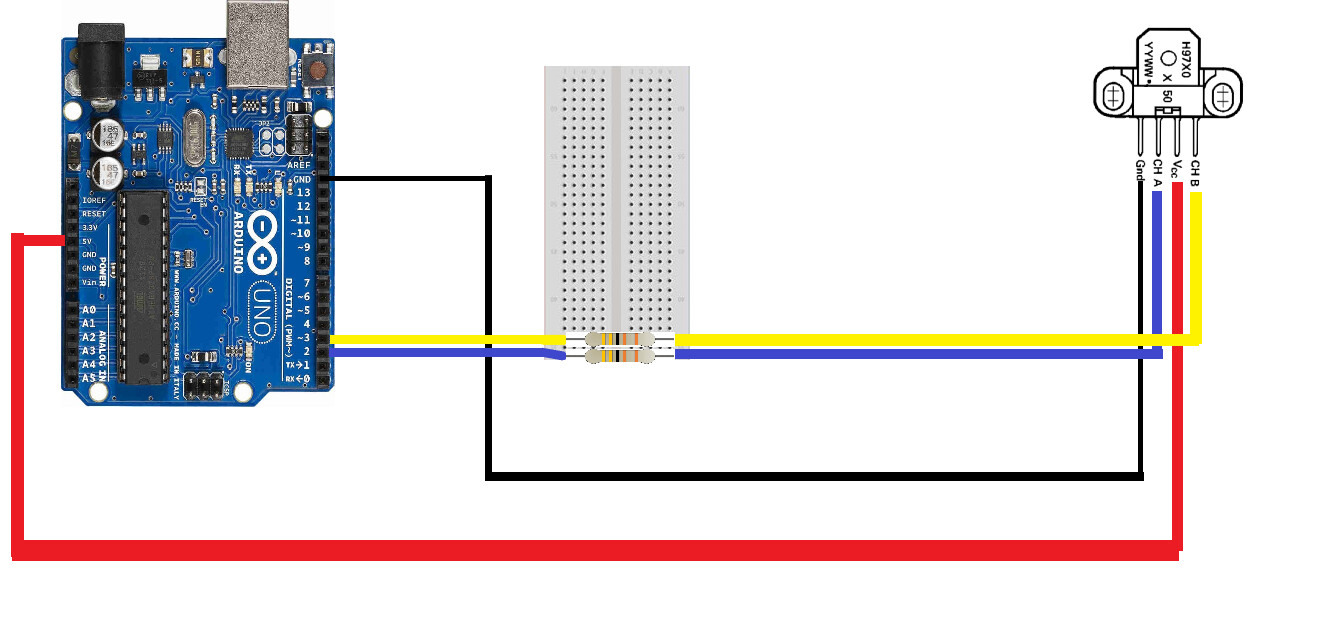
and my circuit is like this:
you’re completely right, i made a mistake, big one actually LoL
i rewired things but still the same result coming up. i don’t know if it’s because of my setup or what.( i mean it’s not that much stable …)
anyway i got myself together and went to buy a AS5045. hope it’ll work.
Hey there, the AS5045 has a SSI interface, which we currently do not support. Not sure how hard it will be to make a driver for it, I’ll see what I can find.
It’s PWM output is supported though, perhaps you can make it work with that…
thank you for the respond
yeah it has pwm and i used it. it works fine
i finally closed the loop and have the motor running with a magnetic sensor. Thanks for the help.
i’m trying to use servo.h library along with the simplefoc but i get strange responds with either gimbal or the servos!
eventhough the servos are not connected to the board, i still don’t get proper function when i have a servo.write in my code along with the foc.
I’m just going to guess here, but it would probably be one of two things:
even if you have the servos connected to different pins, they could be using the same timers and/or clocks as the PWM signals of SimpleFOC. If the servo code changes the timer settings on simplefoc then this will mess up the BLDC driver. You might be able to solve this by having either simpleFOC or the servo use different timers (i.e. pins).
the servo code is taking too long to execute - when running simpleFOC you have to be sure the loopFOC() and move() functions are called very often, say 1000x per second or more… so you have to be very careful what you try to do on the same MCU as well as SimpleFOC.
which timer is the simple foc library using? i dugg into the library a while ago and remember some functions such as _micros and … that where using timer interuppt.
and if i am to change servo library, would it make a difference to use another timer?(i mean i can use a higher frequency interrupt instead of a lower frequency by simply jumping few interrupts to get the desired time)
i ran into this speed problem before. and i added a few move() functions in different places of the code(say 4 5 times in the main loop). it did run the motor smoother but i was wondering what alternatives do i have? and is this a good solution(adding multiple move() in 1 loop)?
i would probably use two arduino nano instead of 1 UNO, considering this noise situation and multiple modules.
For #2, it could be one way to help matters, but it is the loopFOC() function which is most important to call often. The move function can be called a bit less often, especially on a fast MCU, but on an UNO probably better to call both.
This approach can be tricky, because the other code that is being used could do something “big” which takes too long by itself, with no chance to insert your own functions in between. Adding extra calls only works if you’re trying to do many “small” things in the loop. Then you can make sure loopFOC() gets called in-between each thing.
Usually it is better to find “asynchronous” ways of doing things, but this can get quite complex, and on a UNO your possibilities may be limited.
Using 2 or more MCUs where each motor has its own MCU for running simpleFOC, and a “central” MCU coordinates them all, this can be a simpler approach in some ways, leading to simpler code. But you need to design a good communication protocol between the MCUs for things to work well, and this can also be tricky.
Perhaps someone else can comment on the timer question for the UNO (ATMega) - I’d have to look in the code and data sheets, I don’t know enough about this MCU to answer from my knowledge…
thank you very much for ur time.
i’ll probably go with two boards and not changing the servo library
MCUs will not need to communicate. MCU #1 will handle the gimbal motor and controller calculation. just like an inverted pendulum. MCU #2 will handle bluetooth module and two servos.