Hi everyone, I’m trying to learn about Field Oriented Control and I can’t wrap my head around the outputs of sinusoidal modulation and space vector modulation.
I’ll try to briefly explain what I know so far, just in case I’m totally off track.
So, as far as I know, the goal is to generate phase voltages such that the space vector of the stator’s currents always has a direct component (in the dq reference frame) equal to zero (in the most simple case). Since electronically we can’t control currents, we control voltages. So, the outputs of the PIDs are reference voltages Ud and Uq. These voltages are then modulated using sinusoidal modulation or space vector modulation in order to output a voltage for each phase. SVM does that in a more efficient way by adding a triangle wave to the sinusoid. So, in order to apply the analog voltage values [Ua, Ub, Uc] to each phase we use PWM. Since I don’t have a strong background in electronics, here come my doubts:
Suppose that one control loop outputs Ua = 6V (a random value), and our supply voltage is 12V. That means that in phase A we should output a PWM signal with 50% duty cycle. How many times can the PWM signals repeat itself before the next control loop? Is the PWM frequency fixed?
What does it actually mean to apply PWM to each phase? As far as I know, driver boards have a three phase inverter that uses 6 mosfets to commutate between the stator’s states. So, do we actually apply PWM to each gate of the mosfets in order to commutate fast between states, or do we need a driver board that applies PWM directly to the three phases that go into the motor? In the first case, how would we actually determine the switching algorithm given Ua, Ub and Uc? In the source code i can see that you guys implemented a BLDCDriver3PWM class and a BLDCDriver6PWM class but given my poor theoretical background I can’t seem to find the answer there. I think that I can’t really figure out how Ua, Ub and Uc are actually used after they are given as outputs from the modulations.
Thanks to anyone who takes his time to answer these questions
It will retain the duty cycle until the next time the algorithm calculates a new value (which may be the same value, if the shaft is not moving). This is why high “loop speed” is desireable. There is no limit on the number of PWM cycles that can be done since if you time average the signal, it all looks like an analog DC value.
Yes - but you can set it to be different frequencies if you want. You need it to be lower then the switching frequency max for your driver (on BJT based drivers, this is quite low, on MOSFET drivers considerably higher). There is no need to modulate the frequency during use. If the PWM cycle is faster than your control loop, then there is no benefit (other than it not being the limiting factor).
You are saying the same thing twice: You use a controller to apply PWM to the gates (at low voltage logic levels), and the gates then switch PWM from the motor supply voltage to the motor phases. Because of the inductive nature of motors this is smoothed to a more or less analog voltage.
They are calculated from the math shown in the switchcraft/youtube video, and the resulting floating point value is then normalized to the power supply voltage, and then requested from the PWM peripheral inside the microcontroller as a duty cycle (some fraction of the power supply voltage).
Thank you and @Candas1, I have seen that youtube video but not the switchcraft page.
Unfortunately, I still can’t understand how the three outputs of either modulations are used.
I understand (I think) that those three values are generated by the modulations, as shown in BLDCMotor::setPhaseVoltage. In particular, they are phase (to ground) voltages that if normalized with the power supply voltage indicate a duty cycle, like you said.
If I’m getting this correctly, in the SimpleFOC library that is done, for example, in BLDCDriver3PWM::setPwm regardless of the modulation used just before calling _writeDutyCycle3PWM. When _writeDutyCycle3PWM is called, the executed code is hardware specific.
Now, what is piloted by these three duty cycles dc_a, dc_b, dc_c? Do they pilot the gates of the 6 mosfets? If that’s the case, why do we need just three duty cycles? If I’m not mistaken, this part is not modulation dependent, or maybe every driver board decodes these duty cycles using “inverse SVM”?
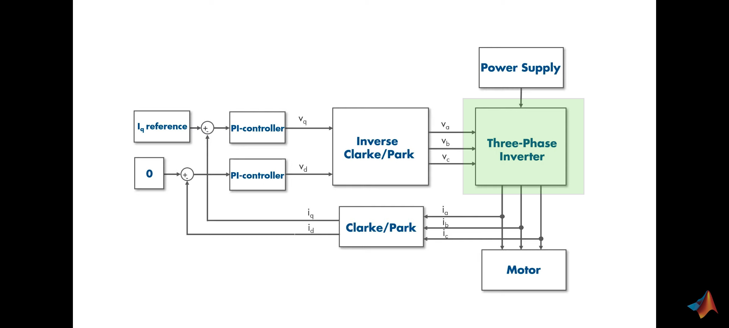
Using the picture below as reference (taken from a Matlab video where they apparently use SPWM), I think that I’m not getting what is happening inside the green square. Maybe my problem is that I don’t know what hardware is inside that green square and how it handles the three inputs.
in 3PWM, there are still 6 MOSFETS, but there is internal digital logic (both the FETs and logic inside the driver IC) that when the PWM input is high, it chooses the upper gate, and when low, chooses the lower gate. In 6PWM, the timers generating the PWM signal are used in complementary mode, where each channel has two lines, that have opposite polarity. In that case, when the signal is high, then the MOSFET is turned on and when low turned off, but due to this complementary structure only one is on at a time. The benefit of this is that you can also specify a dead-time between switching the upper and lower FETs, unlike in 3PWM where the driver IC itself has to handle the dead time. The dead time is necessary to prevent shoot-through of the FET which no current goes into motor and goes through high + low sides at the same time.
TLDR; It’s always three duty cycles for a three-phase motor.
In your picture it is using the phase currents to back-calculate the Q and D current terms as an error signal for the feedback controller. In simpleFOC if you are not using current sense, it uses an estimated current that is calculated by the phase voltage (produced by setPhaseVoltage) multiplied by the phase resistance (given in motor constructor) which gives an estimated current. If you have real current sensing it can use that instead.
Edit: The “three phase inverter” is the 6 switches, be it either a 3PWM motor driver IC or gate driver + 6 discrete FETs. It just moves the digital logic into the high-voltage high-current world of motors.
Thank you, this clears things up quite a bit! So we need a driver board that controls the gates based on the commanded duty cycles. Also, the difference between 3PWM and 6PWM now makes sense. So, is the control logic some sort of black magic, or does it “just” apply the commanded duty cycle to the respective phase’s gates?
For example, let’s say that we have Ua = 3V and supply_voltage = 12V, then dc_a = 3/12 = 0.25. So, does it mean that on the first leg of the inverter, the upper gate stays on for 25% of the PWM period and the lower gate stays on for 75% of that period (with center-alignment)? Also, going back to one of the first questions, does this mean that the PWM frequency has to be higher than or equal to the control loop frequency? In my head I’m thinking that if these two frequencies are equal, then whenever a PWM period finishes, the stator’s phases experienced the wanted voltages and they are ready to experience the next voltage values.
Sorry for the lack of technicality, but this conversation is helping me out a lot. Thanks
Somewhat - it “just” applies the duty cycle to the phases, but also can check if there are driver errors, if the enable pins are pulled down, etc. It’s up to the silicon designers what happens in there but as far as you need to be concerned, it just creates a signal that can be sent to some kind of gate-driver circuit.
Yes!
Yes! No, but it can be a limiting parameter. For example with slow BJT drivers, the switching speed has to be lower, which limits performance.
In terms of 3-PWM, you can consider the driver to be performing a certain amount of “black magic”: in this mode, the driver is doing what is called the “dead-time insertion”. The dead-time is a small amount of time that is inserted in the PWM signal after the switch-off of one side and before the switch-on of the other side.
This “dead-time” is important because the FETs have a certain delay before switching off or on, and you would not want to create a situation where they are both (even partially) on - shoot through.
In 6-PWM, the MCU adds the dead-time into the complementary signals it is emitting to the driver. This allows fine control over the dead-time.
")