Hello folks. I’ve been snooping around this forum for a little while and wanted to share the board I’ve been working on in case someone finds it useful or interesting. KiCad files are here on github
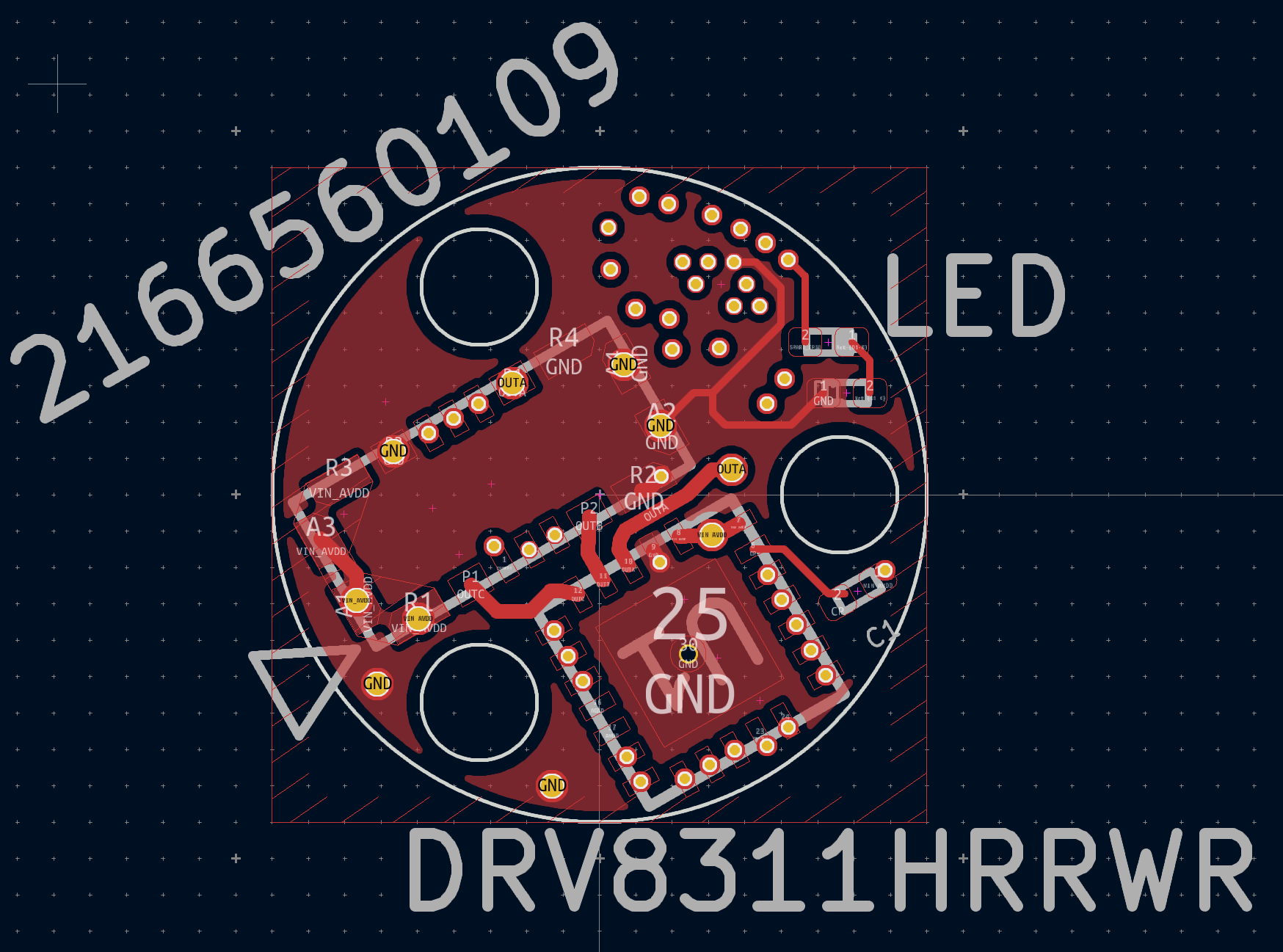
I’m interested in making things as small as possible and I recently discovered some really tiny BLDC motors. They are labeled 0702 size and there are a few companies that make motors in this size class, examples here. Generally they are 9mm outer diameter (less than a centimeter!). I liked seeing the all-in-one FOC boards that people have designed that fit neatly on the bottom of a motor. So I ventured to find out if it is possible to squeeze the motor driver, MCU, angle sensor, and connector into a 9mm circle with mounting holes. And I think I’ve come close! But it’s not really hobbyist friendly anymore. You basically have to use WLCSP (wafer level chip scale package) components which are so tiny. The ball grid array pitch on the STM32 I chose is 0.35mm. The biggest challenge is actually selecting a connector. The best option I could find is the Molex connector P/N: 2166560109. Though if you look at the data sheet I’m actually not using it as intended so that I can maybe eke out 2 more power pins. My biggest regret is that there is no way to fit a connector to plug the motor in directly to the board. My current thought is that I will make an ribbon cable (flex PCB) with the mating molex connector, the mating motor connector, debug, serial, and power connectors.
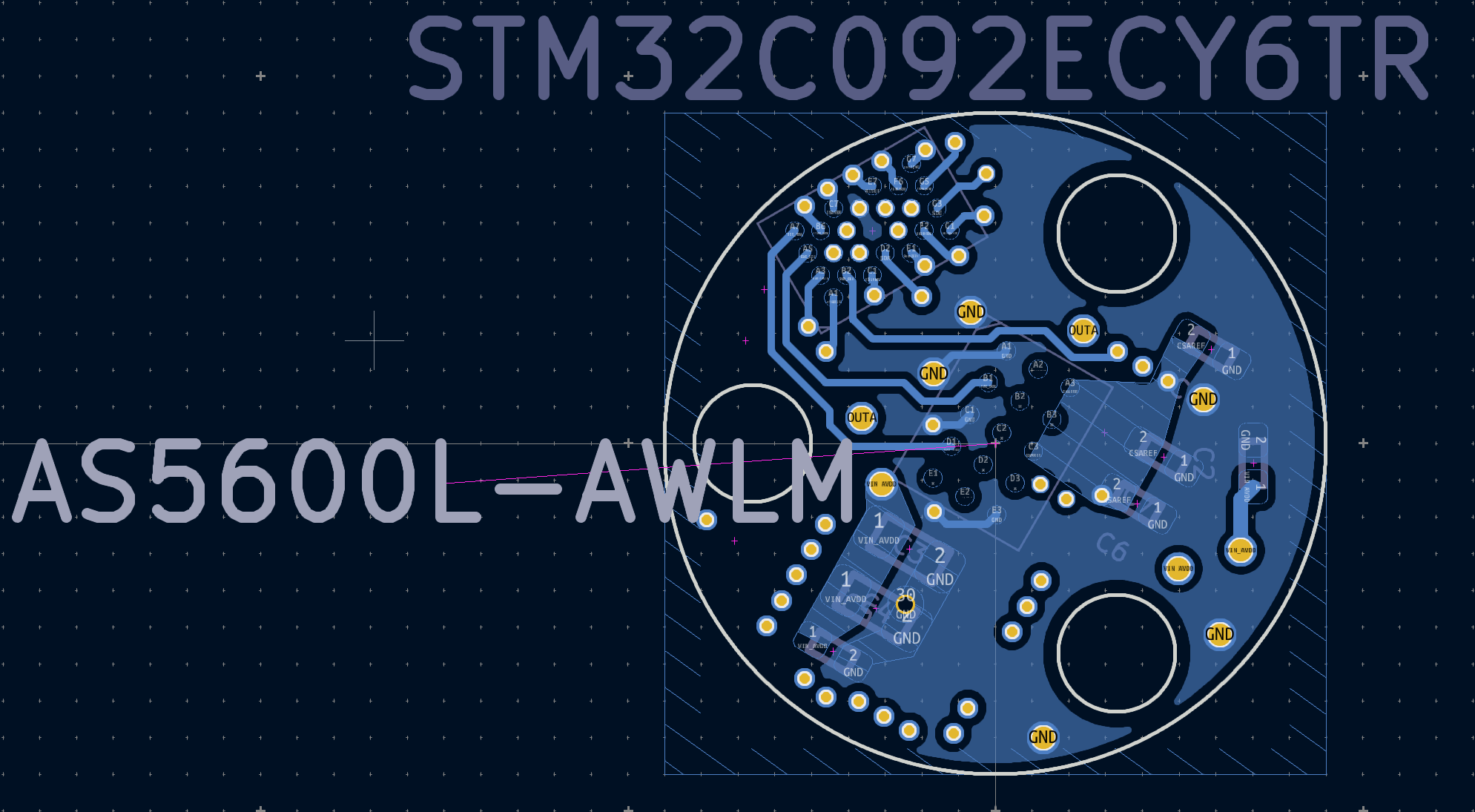
MCU: STM32C092ECY6TR
SENSOR: AS5600L-AWLM
DRIVER: DRV8311HRRWR
Some other oddities: JLCPCB is having a sale on 6 layers boards so for no good reason I decided to try to make this layout compatible with both the SPI and PWM models of the DRV8311 chip. I checked the STM32 pinouts and this should work. Also I didn’t route the STM32 RST pin anywhere. If you wanted to select just the SPI or the PWM version, this board should fit in just 4 layers. Probably without capped tiny vias in pads under the STM32 too. Big bonus there. Lastly, I have no idea what the current limit would be with this design. Certainly not very high. I suspect the traces carrying motor current would be the limiting factor.
I haven’t sent this to get manufactured yet. I was going to have JLCPCB do the assembly too because I have not been able to get the WLCSP to seat properly at home. Just wanted to share with you guys cause I know there was some interest last time someone posted a very small FOC board. Who knows if it will work, it will be fun finding out at least.