ParaTrain - a paragliding simulation and training device

So, here is the SimpleFOC based hobby project I have been working on for quite a while now. It is a simulator and training device for paragliding. It was virtually all new to me, which made it more challenging, but also very interesting. I have solid knowledge of electronics and have developed software for most of my life, but power electronics, motors, motor drivers, CAN bus and everything else involved here where white spots on my map, not even speaking of the physics behind such a simulator. Many paraglider pilots have simulators to play with their harnesses, but only very few will have one which is active, like mine:


(sorry for the mess in the background…)

Right now it performs two tasks. It serves as a training device by simulating the forces on the break lines as perceived when flying through turbulent air and it serves as input device for an online paragliding simulation game.

For the first task the torque of the motors is controlled to exert increasing forces the further down the breaks are pulled. There is a “neutral” point, where the force is 20N and this is the normal flying position. To simulate turbulances, this neutral point is randomly moved up or down and the pilot has to keep the force constant in order to fly straight. Forces and weight shifts are evaluated and a final score is given at the end of each training session. For the second task, the online simulator xcsim is controlled via a bluetooth connection to a PC and input from the breaklines and weight shifts is passed on to the online simulation.

The technical realisation connects several units with a CAN bus. The two break units are based on B-G431B-ESC1 boards, AS5047 sensors - on my first self designed PCB since 35 years, T-motor G60 kv55 motors, a lot of 3D printed stuff and of course SimpleFOC (torque mode, FOC current, sensor calibration).


Another unit contains 5V power supply, gyro sensor, signal distribution and motor temperature measurement, all built around an ESP32

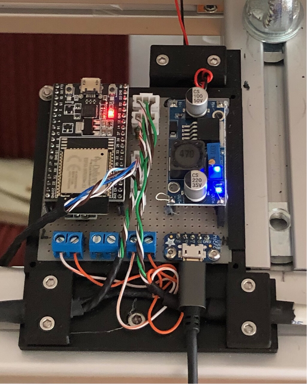
Finally, the central control unit provides a very basic user interface, sends all the training commands to the motors and communicates with a PC using Bluetooth. This unit is also based on an ESP32.

The main difficulties which I encountered during the development - apart from lacking knowledge - were broken cheap CAN transceivers on breakout boards, dealing with strong BEMF if the pilot pulls the strings fast (solved with an active shunt, thanks @Valentine !), a loose magnet which still gave reasonable angle readings from the sensor (solved with a lot of help from this great forum!) and finding the right strategy for pulling the break lines in a realistic way. The last point caused some major software redesign since I started with position mode, which allowed me to nicely control the speed at which the neutral point varied, but the resulting motion never felt smooth, so I moved to torque mode with variable ramp parameters, which is very smooth now. Of course, I redesigned the mechanics several times and experimented with different motors too.

Next steps:
- Gain more real world flying experience (I am still a beginner) in order to tune the behavior even better.
- Simulate movements of the seatboard caused by wind/thermal forces. No idea yet how I will model this, but I know already it will require very strong motors if it shall be realistic…

If there are other paraglider pilots here with similar projects or ideas, I am very open to discussion. I had planned to make the design open source, but I don’t know if I will ever find the time required to clean it up sufficiently and to document everything so that other people could replicate the design.

Happy landings,
Chris

7 Likes

That’s a really amazing project!! It’s clear you’ve put so much work into it, and it looks like you’ve made something really impressive, and quite unique too. Congratulations!!!

Very impressive, thank you for sharing.

Cheers,
Valentine

Please share a video! This might just be the coolest SimpleFOC project so far :slight_smile:

Thanks for the compliment, but it is by far not as spectacular as it may sound, all your robots are certainly far more complex. After all, I am just pulling on two strings. With more experience it would have been easy. Anyway, I have learned tons of new things and that was real fun! Once I have the seatboard movements implemented, it will be more interesting, but that is more something for the next winter, it is outdoor season now!

3 Likes

Wow too bad that I’ve only just seen your project here. I had the same Idea in mind and I already ordered the parts :slight_smile:

Ill try it with the 90KV eaglepower 8308 motor. And (also bec Ive seen your porject here too lare) Ill try to run it with a ODrive board and code.

I have the same aim in mind: Im more or less a beginner in paragliding and I can not go paragliding enough to train my muscle memory the active steering in turbulent air. Therefore I will build the simulator for myself.

Is there any way I could reach you directly, Chris? Im from Hamburg, Germany btw :slight_smile:

Would be great to share some ideas and ofc I would like to learn a bit from your project.

And Yes I already thought about a system to move the harness with linear actuators

1 Like

Hi Lukas, I‘ll send you a DM.

I feel it is time for a short update before we enter any discussion, but let me start with a clear warning: Depending on how far you want to take it, this endeaver is far more complex, time consuming and expensive as you might think at the beginning, however, it is also a lot of fun of course!
Since my initial presentation here, I made several big steps forward. I can now not only simulate variable tension of the break lines, but I can also simulate roll movements of the harness, I can use it with a Meta Quest 3 to control GliderSim (a really nice VR paragliding simulation game) through BLE and I can receive force feedback from the VR game via BLE (my sim rig declares itself to the PC as a Bluetooth connected gamepad). Also, I made PCBs for the main user interface (display, buttons, two rotary encoders, runs all the controll software, communications and very simple physical flight model) and the sensor unit (IMU, temp sensors, CAN bus distribution, some power management). The next big step will be simulation of pitch movements, which is mostly a trade off between space for long levers and motor size, still quite some way to go there. Currently it looks as in the messy picture below.
The experience so far is:

  • Mechanical design is reasonable, use of standard Item profiles was a good decision because of the flexibility.
  • Especially for the break lines, haptics are very important, it is essential to use very low cogging motors. Motors must also be fairly strong and react fast to be realistic.
  • Managing BEMF is absolutely essential. Otherwise, if you pull hard on the breaks, you create significant overvoltage and destroy the electronics. I had to learn it the hard way. Current solution is usage of a shunt regulator as proposed by @Valentine. I am just experimenting with a regulator based on a MOSFET and a TL431 (smaller, cheaper, less heat), but Valentine’s proposal I would call well proven.
  • Modified (SPI, replaced potentiometer by an NTC) B-G431B-ESC1 drivers are well suitable so far although it is really tempting to make my own drivers, but too many interesting things to do…
  • Communication between all the MCUs via CAN bus works very nicely.
1 Like

I had a look at the motors you are planning to use, but could not find information regarding pole pairs (probably “enough”) or torque. By the look, these are more made for drones, where cooling is implicite. Will be interesting to see how they behave in a simulator. You’ll need a strong power supply probably with these.

Thank you so much for your reply and the update!

So good to see that there is another person out there with the same crazy ideas.

Just to understand it correctly, you installed a 3rd motor to tilt the harness, right? So the motor is strong enough for that? And it seems like there are two overlapping movements or degrees of freedom of the harness that enables tilting it?

I though that two actuators were needed to lift and lower the two suspension points of the harness (which represents the lift of each side of the glider)

It is also interesting to see that you are missing the pitch movement more than the general feeling of getting lifted (or lowered).

Again, thank you so much for all the info!

The third motor sits right in the middle of the rig, the cord is between the two sides of the rig and the spool on the motor lifts one side and lowers the other one (well, lowering is performed by gravity actually). See this picture:


Due to the two pulleys on top I only require half the force. Also, the central pivot point has the advantage that I do not need to lift my entire weight with the motors.

Further to that I would not say that I miss pitch more than G-forces, but I think it is more prevalent in thermals. Also, I don’t see how I could easily implement the G forces caused by lift since it would require a lot of space and very strong motors ($$$). Pitch is simply a lower hanging fruit. Really important were the roll movements though!

Yet another thing to simulate in combination with VR games is pushing the speedbar. This is pretty simple however (just a multi turn potentiometer) and my sensor PCB is already ready for that. Had no time for the mechanics yet and I do not really miss it.

For pitch I am planning the same concept as for roll, just 90 deg rotated. The motor will sit in the center on top, above the top swivel, which will then be hung below the motor. I still need to measure the required forces though.

1 Like