Page not found, - commander motor commands needed

I am trying to get constant velocity mode working with. SimpleFOC arduino shield board with an AS5600 I2C encoder and magnet.

I’ve hit a wall because the page for the motor commander commands is 404, not found. The ? command that is supposed to list all commands doesn’t seem to work.

I tried the constant velocity example, modified it for the I2C sensor ok, and it initializes, but there appears to be an error in the example code, it says dotarget is not defined in this context, which is true. I have no idea what dotarget is supposed to be doing, I usually use micropython. I tried removing it and hard coding a constant velocity (100) into the code, but cannot get it moving. I’ll post the code in a second, I am on the wrong computer right now.

What I am after is smooth, quiet motion up to about 4000 rpm. I need to be able to reverse direction and have relatively good acceleration. This is just for a fan. I know simpleFOC may be overkill, but I was planning on using the lepton, which is similar in price to typical sensorless foc boards anyway, and I might need anti cogging. UPS lost the package so I am trying to get on with things with this arduino shield instead, hoping I can get the code working and verify the system can provide quiet, smooth operation at suitable speed and efficiency (can’t have the motor overheating).

I can tune the PID loop ok, I am familiar with that. I do not really need a PID and wouldn’t mind disabling that.

But I’ve hit a wall here, I need those commands. Also, do I need to use the system in velocity control mode for smooth high velocity motion?

Here is the best I could do with the code to get the motor to run at a constant velocity #include <SimpleFOC.h>

// magnetic sensor instance - SPI
MagneticSensorI2C sensor = MagneticSensorI2C(0x36, 12, 0x0E, 4);

// BLDC motor & driver instance
BLDCMotor motor = BLDCMotor(11);
BLDCDriver3PWM driver = BLDCDriver3PWM(9, 5, 6, 8);

// target variable
float target_velocity=0;
// commander interface
Commander command = Commander(Serial);
void onTarget(char* cmd){ command.scalar(&target_velocity, cmd); }

void setup() {
// initialize encoder hardware
sensor.init();
// link the motor to the sensor
motor.linkSensor(&sensor);

// power supply voltage
// default 12V
driver.voltage_power_supply = 12;
driver.init();
// link the motor to the driver
motor.linkDriver(&driver);

// set FOC loop to be used
// MotionControlType::torque
// MotionControlType::velocity
// MotionControlType::angle
motor.controller = MotionControlType::velocity;

// controller configuration based on the control type
// velocity PI controller parameters
// default P=0.5 I = 10
motor.PID_velocity.P = 0.2;
motor.PID_velocity.I = 20;
// jerk control using voltage voltage ramp
// default value is 300 volts per sec ~ 0.3V per millisecond
motor.PID_velocity.output_ramp = 1000;

// velocity low pass filtering
// default 5ms - try different values to see what is the best.
// the lower the less filtered
motor.LPF_velocity.Tf = 0.01;

//default voltage_power_supply
motor.voltage_limit = 6;

// initialize motor
motor.init();
// align encoder and start FOC
motor.initFOC();

// monitoring port
Serial.begin(115200);
Serial.println(“Motor ready.”);
_delay(1000);
}

void loop() {
// iterative FOC function
motor.loopFOC();

// 0.5 hertz sine wave
//target_velocity = sin( micros()*1e-6 2M_PI * 0.5 );
motor.move(200);

// iterative function setting the velocity target
command.run();
}

This is the code I tried to use to do general testing using the commander, but I cannot proceed because there is no documenation available for the commands to control the motor
#include <SimpleFOC.h>

// magnetic sensor instance - SPI
MagneticSensorI2C sensor = MagneticSensorI2C(0x36, 12, 0x0E, 4);

// BLDC motor & driver instance
BLDCMotor motor = BLDCMotor(11);
BLDCDriver3PWM driver = BLDCDriver3PWM(9, 5, 6, 8);

// commander interface
Commander command = Commander(Serial);
void onMotor(char* cmd){ command.motor(&motor, cmd); }

void setup() {

// initialise magnetic sensor hardware
sensor.init();
// link the motor to the sensor
motor.linkSensor(&sensor);

// driver config
// power supply voltage [V]
driver.voltage_power_supply = 12;
driver.init();
// link driver
motor.linkDriver(&driver);

// set control loop type to be used
motor.controller = MotionControlType::torque;

// contoller configuration based on the control type
motor.PID_velocity.P = 0.2;
motor.PID_velocity.I = 20;
motor.PID_velocity.D = 0;
// default voltage_power_supply
motor.voltage_limit = 12;

// velocity low pass filtering time constant
motor.LPF_velocity.Tf = 0.01;

// angle loop controller
motor.P_angle.P = 20;
// angle loop velocity limit
motor.velocity_limit = 50;

// use monitoring with serial for motor init
// monitoring port
Serial.begin(115200);
// comment out if not needed
motor.useMonitoring(Serial);

// initialise motor
motor.init();
// align encoder and start FOC
motor.initFOC();

// set the inital target value
motor.target = 2;

// define the motor id
command.add(‘A’, onMotor, “motor”);

// Run user commands to configure and the motor (find the full command list in docs.simplefoc.com)
Serial.println(F(“Motor commands sketch | Initial motion control > torque/voltage : target 2V.”));

_delay(1000);
}

void loop() {
// iterative setting FOC phase voltage
motor.loopFOC();

// iterative function setting the outter loop target
// velocity, position or voltage
// if tatget not set in parameter uses motor.target variable
motor.move();

// user communication
command.run();
}


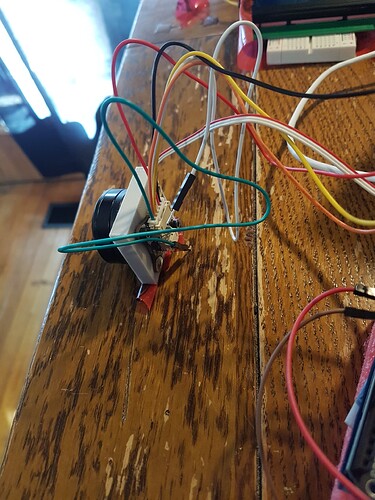
There is a 6mm nib magnet in there although you cannot see it.

Hey, there seems to be something wrong with the links. Thanks for pointing it out, we’ll try to fix it soon.

In the meantime, I think most of what you’re looking for is here:

Thanks man, I gave them a try, but it is not processing the commands correctly. It says the value has been changed when I read back the value, but it doesn’t seem to actually change.
The tendency to oscillate does not change no matter what I set the PID gain values to .

This is the output of the serial, using the sketch I pasted above for general purpose commands: 14:56:13.597 → MOT: Monitor enabled!
14:56:13.597 → MOT: Init
14:56:14.075 → MOT: Enable driver.
14:56:15.065 → MOT: Align sensor.
14:56:18.558 → MOT: sensor_direction==CW
14:56:18.558 → MOT: PP check: fail - estimated pp: 6.22
14:56:19.282 → MOT: Zero elec. angle: 4.76
14:56:19.969 → MOT: No current sense.
14:56:19.969 → MOT: Ready.
14:56:19.969 → Motor commands sketch | Initial motion control > torque/voltage : target 2V.
14:58:27.561 → A:motor
14:58:29.652 → A:motor
14:58:37.163 → PID vel| P: 0.200
14:59:03.300 → PID vel| P: 0.020
14:59:30.010 → PID curr q| P: 2.000
14:59:42.250 → PID curr q| P: 0.500
15:00:08.447 → PID curr d| P: 2.000
15:00:14.111 → PID curr d| P: 0.200
15:00:32.943 → PID angle| P: 20.000
15:00:37.171 → PID angle| P: 2.000
15:01:11.156 → PID curr q| I: 100.000
15:01:17.260 → PID curr q| I: 10.000
15:01:41.271 → PID curr d| I: 100.000
15:01:52.218 → PID curr d| I: 10.000
15:02:12.381 → PID vel| I: 20.000
15:02:18.651 → PID vel| I: 2.000
15:02:31.224 → PID angle| I: 0.000

I reduce the gain by 5 or ten or whatever, and it makes zero difference. Ideas?

Tried to get the graphical interface thing working, but it doesn’t work in about five different ways. One error, if I manage to solve that there is another one. Says it can’t find the package in the repository. Says to go search the website. I search, nothing found. Jeeze.

(base) PS C:\Users\anthony> conda create -n simplefoc python=3.6.0
Collecting package metadata (current_repodata.json): failed

CondaHTTPError: HTTP 000 CONNECTION FAILED for url https://repo.anaconda.com/pkgs/main/win-64/current_repodata.json
Elapsed: -

An HTTP error occurred when trying to retrieve this URL.
HTTP errors are often intermittent, and a simple retry will get you on your way.

If your current network has https://www.anaconda.com blocked, please file
a support request with your network engineering team.

‘https//repo.anaconda.com/pkgs/main/win-64’

(base) PS C:\Users\anthony> conda create -n simplefoc python=3.6.0
Collecting package metadata (current_repodata.json): done
Solving environment: failed with repodata from current_repodata.json, will retry with next repodata source.
Collecting package metadata (repodata.json): done
Solving environment: failed

PackagesNotFoundError: The following packages are not available from current channels:

  • python=3.6.0

Current channels:

To search for alternate channels that may provide the conda package you’re
looking for, navigate to

https://anaconda.org

and use the search bar at the top of the page.

(base) PS C:\Users\anthony> conda activate simplefoc

EnvironmentNameNotFound: Could not find conda environment: simplefoc
You can list all discoverable environments with conda info --envs.

Invoke-Expression : Cannot bind argument to parameter ‘Command’ because it is an empty string.
At C:\Users\anthony\anaconda3\shell\condabin\Conda.psm1:76 char:36

  •     Invoke-Expression -Command $activateCommand;
    
  •                                ~~~~~~~~~~~~~~~~
    
    • CategoryInfo : InvalidData: (:slight_smile: [Invoke-Expression], ParameterBindingValidationException
    • FullyQualifiedErrorId : ParameterArgumentValidationErrorEmptyStringNotAllowed,Microsoft.PowerShell.Commands.Invo
      keExpressionCommand

(base) PS C:\Users\anthony>

I can’t really help with the SimpleFOCStudio except to say python can be a big pain…

This is not a good sign. This indicates there is a problem with the sensor. Perhaps sensor is not well aligned, using a bad magnet or getting noise on the signal lines, or the air gap is too big/small. Or the alignment voltage is too low or too high If you can get the PP check to pass this would be a good first step.

In torque voltage mode you can set the voltage and the motor should turn at the speed natural for this voltage/load situation.
Setting the PID doesn’t make a difference in this mode, the PID isn’t used.

The PID comes into play when using velocity mode.

hm, the air gap is 1 mm. The magnet is very slightly not aligned but I wasn’t aware it was critical. It’s resting in a printed holder. Googling indicates PP check stands for pole pair check? The motor is not drawing much current, but it tends to start oscillating if left for a few seconds. If I rotate it it resists rotation ,but only until the next step, that is I can rotate it a small part of a rotation and it snaps back, but if I rotate it enough, it snaps into a new position. Thus indicating that the system is only applying a passive current and not trying to regulate angular position using the encoder. However that it is oscillating indicates there is some kind of feedback loop, apparently it is reading the encoder.

How am I supposed to be aligning the magnet? Does it have to be in a particular position relative to the rotor? I thought the system would automatically measure the angle of the magnet relative to the magnets in the rotor.

I tried moving the motor wires well away from the sensor data wires but it makes no difference.

Maybe I have to tell it information about the number of pole pairs in the motor or something? I have no idea what those figures are for this motor.

I ran the pole pair estimator example, and it seems to work fine. 17:03:20.788 → Pole pairs (PP) estimator
17:03:20.788 → -
17:03:20.788 →
17:03:28.786 → Estimated PP : 7
17:03:28.786 → PP = Electrical angle / Encoder angle
17:03:28.786 → 1080.00/154.07 = 7.01
17:03:28.786 →
17:03:28.786 → If PP is estimated well your motor should turn now!
17:03:28.820 → - If it is not moving try to relaunch the program!
17:03:28.820 → - You can also try to adjust the target voltage using serial terminal!
17:03:35.196 →
17:03:35.196 → Motor ready.
17:03:35.196 → Set the target voltage using serial terminal:

It turns fine but emits a serious humming noise.

Ok, I fixed it. There is a problem with the example code. the line where it says
MagneticSensorI2C sensor = MagneticSensorI2C(0x36, 12, 0x0E, 4);

needs to say:
MagneticSensorI2C sensor = MagneticSensorI2C(0x36, 12, 0X0C, 4);

I just compared the two sketches. I have no idea what that hex value is supposed to mean.

The motor turns now, will experiment with constant torque mode.

Ok, so the general purpose code now sort of works, copied below for anyone else that might want it, but it only works in voltage torque mode, and that is definitely too loud, that is obvious.

I need to try the current torque modes, but they don’t work. When I send the code to use those modes and set a setting, it says it processed the command but the motor stays still. There is some current flowing still. However if I disable the motor it turns the current off and wont’ turn it back on again even if I enable the motor again using the relevant command.

It said in the output when the commander was starting that current sense was not enabled or working for some reason. IDK how to enable it? There might have been something useful in the other commander codes docs, but they are almost all not found.

I just have to try the current control modes and see if they are too loud.

IIRC the lepton doesn’t have current sense, so IDK if I can use those modes with it. If not I can’t use it.

#include <SimpleFOC.h>

// magnetic sensor instance - SPI
//old MagneticSensorI2C sensor = MagneticSensorI2C(0x36, 12, 0x0E, 4);
MagneticSensorI2C sensor = MagneticSensorI2C(0x36, 12, 0X0C, 4);
// BLDC motor & driver instance
BLDCMotor motor = BLDCMotor(7);
BLDCDriver3PWM driver = BLDCDriver3PWM(9, 5, 6, 8);

// commander interface
Commander command = Commander(Serial);
void onMotor(char* cmd){ command.motor(&motor, cmd); }

void setup() {

// initialise magnetic sensor hardware
sensor.init();
// link the motor to the sensor
motor.linkSensor(&sensor);

// driver config
// power supply voltage [V]
driver.voltage_power_supply = 12;
driver.init();
// link driver
motor.linkDriver(&driver);

// set control loop type to be used
motor.controller = MotionControlType::torque;

// contoller configuration based on the control type
motor.PID_velocity.P = 0.2;
motor.PID_velocity.I = 20;
motor.PID_velocity.D = 0;
// default voltage_power_supply
motor.voltage_limit = 12;

// velocity low pass filtering time constant
motor.LPF_velocity.Tf = 0.01;

// angle loop controller
motor.P_angle.P = 20;
// angle loop velocity limit
motor.velocity_limit = 50;

// use monitoring with serial for motor init
// monitoring port
Serial.begin(115200);
// comment out if not needed
motor.useMonitoring(Serial);

// initialise motor
motor.init();
// align encoder and start FOC
motor.initFOC();

// set the inital target value
motor.target = 2;

// define the motor id
command.add(‘A’, onMotor, “motor”);

// Run user commands to configure and the motor (find the full command list in docs.simplefoc.com)
Serial.println(F(“Motor commands sketch | Initial motion control > torque/voltage : target 2V.”));

_delay(1000);
}

void loop() {
// iterative setting FOC phase voltage
motor.loopFOC();

// iterative function setting the outter loop target
// velocity, position or voltage
// if tatget not set in parameter uses motor.target variable
motor.move();

// user communication
command.run();
}

I think I may have found a way to enable current sense, but now the sketch is too big for the uno.
Global variables use 1685 bytes (82%) of dynamic memory, leaving 363 bytes for local variables. Maximum is 2048 bytes.
Sketch too big; see https://support.arduino.cc/hc/en-us/articles/360013825179 for tips on reducing it.
Error compiling for board Arduino Uno.

I thought this software was made for this shield which is made for the uno.

code:
#include <SimpleFOC.h>

InlineCurrentSense current_sense = InlineCurrentSense(0.01, 50.0, A0, A2);
// magnetic sensor instance - SPI
//old MagneticSensorI2C sensor = MagneticSensorI2C(0x36, 12, 0x0E, 4);
MagneticSensorI2C sensor = MagneticSensorI2C(0x36, 12, 0X0C, 4);
// BLDC motor & driver instance
BLDCMotor motor = BLDCMotor(7);
BLDCDriver3PWM driver = BLDCDriver3PWM(9, 5, 6, 8);

// commander interface
Commander command = Commander(Serial);
void onMotor(char* cmd){ command.motor(&motor, cmd); }

void setup() {
current_sense.init();
current_sense.gain_b *= -1;

Serial.begin(115200);
Serial.println(“Current sense ready.”);
// initialise magnetic sensor hardware
sensor.init();
// link the motor to the sensor
motor.linkSensor(&sensor);

// driver config
// power supply voltage [V]
driver.voltage_power_supply = 12;
driver.init();
// link driver
motor.linkDriver(&driver);

// set control loop type to be used
motor.controller = MotionControlType::torque;

// contoller configuration based on the control type
motor.PID_velocity.P = 0.2;
motor.PID_velocity.I = 20;
motor.PID_velocity.D = 0;
// default voltage_power_supply
motor.voltage_limit = 12;

// velocity low pass filtering time constant
motor.LPF_velocity.Tf = 0.01;

// angle loop controller
motor.P_angle.P = 20;
// angle loop velocity limit
motor.velocity_limit = 50;

// use monitoring with serial for motor init
// monitoring port
Serial.begin(115200);
// comment out if not needed
motor.useMonitoring(Serial);

// initialise motor
motor.init();
// align encoder and start FOC
motor.initFOC();

// set the inital target value
motor.target = 2;

// define the motor id
command.add(‘A’, onMotor, “motor”);

// Run user commands to configure and the motor (find the full command list in docs.simplefoc.com)
Serial.println(F(“Motor commands sketch | Initial motion control > torque/voltage : target 2V.”));

_delay(1000);
}

void loop() {
PhaseCurrent_s currents = current_sense.getPhaseCurrents();
float current_magnitude = current_sense.getDCCurrent();
Serial.print(currents.a1000); // milli Amps
Serial.print(“\t”);
Serial.print(currents.b
1000); // milli Amps
Serial.print(“\t”);
Serial.print(currents.c1000); // milli Amps
Serial.print(“\t”);
Serial.println(current_magnitude
1000); // milli Amps
// iterative setting FOC phase voltage
motor.loopFOC();

// iterative function setting the outter loop target
// velocity, position or voltage
// if tatget not set in parameter uses motor.target variable
motor.move();

// user communication
command.run();
}

Hey, glad you found the problem! Sounds like you’re making good progress.

Before trying current sense and torque-current mode, be sure to try velocity mode and tune the PID for this.

But it seems you’ve also just discovered that the UNO is not a very powerful MCU. You’re unlikely to fit SimpleFOC with commander and current sensing unless you hack around quite a bit to minimise the code size.
And in terms of the performance it is very slow, so not the best MCU if you’re trying to optimize for silent operation…

I’d use something faster. STM32s are nice, as are ESP32 MCUs. Or if you prefer Arduino products, the newer Nano 33s or MKR boards are all 32 bit MCUs and more powerful.

If ups had not lost the package I would be using the lepton. I spent hundreds of dollars and waited for more than a month for that stuff,

The lepton uses a STM32G031. It’s pretty clear that modularity is good but it may be taking g things a bit far to roll ones own motor driver. It’s expensive anyway and the mcu has to be dedicated so there is little point in mixing and matching.

The logical approach is leptons with current sending pre loaded with the right firmware… these shields are not a good approach.

Are you able to tell me if the lepton could give me quiet fan functionality? That’s all I want to know.

Clearly voltage based torque mode won’t do, I don’t think it will work whether it’s in velocity or torque mode. I can go back and try constant velocity mode but I don’t see how that would make less noise than constant torque (voltage) mode.

All i want is an answer as to whether this can even do anything even close to what I need. I’ve spent huge amounts of time and substantial money on trying just to get an answer to this question and this is not economical.

I have a teensy, which I have found is mostly usually compatible with the same code, if I just change the pin numbers. However chances are pretty high with complex code that at least once thing will not work. Also I need to mine out all the information I need on the pin connections from the shield to the teensy. I may do that later today or tomorrow but very high chance something will go wrong.

Nope, doesn’t work. Completly useless error message, no way to solve anything or make any progress. just" error compiling".

In file included from C:\Users\anthony\Documents\Arduino\libraries\Simple_FOC\src/SimpleFOC.h:116:0,
from C:\Users\anthony\Documents\Arduino\sketch_jan08bmotortest1with_current_sense\sketch_jan08bmotortest1with_current_sense.ino:1:
C:\Users\anthony\Documents\Arduino\libraries\Simple_FOC\src/communication/StepDirListener.h:56:5: error: ‘PinStatus’ does not name a type
PinStatus polarity = RISING; //!< polarity of the step pin
^
sketch_jan08bmotortest1with_current_sense: In function ‘void setup()’:
sketch_jan08bmotortest1with_current_sense:66: warning: ISO C++ forbids converting a string constant to ‘char*’
command.add(‘A’, onMotor, “motor”);
^
Using library Simple_FOC at version 2.2.3 in folder: C:\Users\anthony\Documents\Arduino\libraries\Simple_FOC
Using library SPI at version 1.0 in folder: C:\Program Files (x86)\Arduino\hardware\teensy\avr\libraries\SPI
Using library Wire at version 1.0 in folder: C:\Program Files (x86)\Arduino\hardware\teensy\avr\libraries\Wire
Error compiling for board Teensy 4.0.

I chopped out the current sensing etc, trimmed things down as much as I could, same error.

There’s a bunch of different Teensys, we support some of them. They are very fast MCUs, but probably not as widely used and therefore not as well tested as some of our other MCU types.

You’ve asked this before, and I think I’ve answered a couple of times before, and I fear now that no one can really tell you in advance. You seem to have very specific requirements, and so I don’t think people really know how to answer this question in a way that meets your expectations.

In principle you will have a few sources of noise:

  1. The fan itself. its shape, size and the speed it turns will generate noise, even if driven by a totally inaudible drive system.
  2. The motor’s mechanical construction - hopefully it has good bearings and isn’t rusty.
  3. The motor’s windings when driven by the commutation. PWM speeds should be above 20kHz to ensure you can’t hear the commutation. The driver should support sufficiently high switching speeds.
  4. The motor’s physical construction - cogging, etc. E.g. a 7PP motor will probably be louder than one with higher pole counts, as higher pole counts turn more smoothly.
  5. The control - is it regular and smooth, are the PWM signals phase correct, are other tasks interfering with the real-time control, is the sensor accurate, well-placed and reliable, etc…
  6. Possibly electrical noise caused by power supply, inductors, etc…

I think you’ll only really get input on #5 here, the others pretty much depend on your hardware.

Regarding #5, as I’ve also mentioned, I believe, I can confirm that I can drive BLDCs like an Emax GB4114 (47KV, 10Ω, 11 pole pairs) at around 10V, using decent MCUs (so not an UNO) and 14 bit sensors like the AS5048A at low speeds (lets say <10rad/s) and you can’t hear them at all. Even when you put your ear right next to them you hear only the barest whisper of a sound.
When I increase the speed, you begin to hear the motor a bit more, but the fan of my PSU is considerably louder, though further away.
I don’t know if that helps you.

Regarding the modes, I believe once they are tuned well, the noise will be caused by the speed the motor is going at and not the mode used to achieve that speed. So it should not matter whether it is torque-voltage, velocity or torque-current mode. As long as it is closed loop, FOC. Open loop is less efficient and louder.

Well, actually it says:
C:\Users\anthony\Documents\Arduino\libraries\Simple_FOC\src/communication/StepDirListener.h:56:5: error: ‘PinStatus’ does not name a type

So it’s telling you that the Teensy core does not define the PinStatus enum type. It’s a common thing, some MCU platforms define it and some don’t.

But it does mean the code won’t just run on this core without fixing it first.