If the simplefoc controller is run in full power( i.e. no pulse width modulation) mode, is the output a three phase sine wave and can the frequency be modulated?
In other words, can it function like a variable frequency drive controller?
From my point of view, SimpleFOC is a library which can be used to produce a “variable frequency drive” for BLDC motors.
VFD is usually associated with AC motors, the larger things you find in factories, large tools, construction equipment, etc… but at its core it simply means a motor controller that operates the motor by varying the frequency of the signals to its windings.
Like AC induction motors, BLDC motors can be moved by providing a sinusoidal commutation pattern to the motor windings. In terms of how this is exactly done, there are differences, which I can’t really get into as I’m not really an expert for either type of motor, but especially I don’t know much about AC motors.
For BLDC motors, they can also be moved with “block commutation” - which is no longer a sinusoidal pattern but a trapezoidal one. Which type is better depends a bit on the type of the motor and the application, but in general terms a BLDC motor can be moved with either type of commutation.
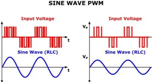
The PWM has little to do with all this - the PWM is used to set a voltage to the motor’s phases - because the motor is an inductive, “slow changing” load it will “smooth” the PWM signal, and instead it will “see” an analog voltage proportional to the PWM duty cycle.
The PWM frequency will normally be several times higher than the commutation frequency.
In block commutation you could use PWM, or you could work without PWM (depending also on your hardware), but to do the sine commutation PWM is a must.
While I’ve not looked inside one, I assume very much a commercial VFD drive also uses PWM in some way to convert its digital controller’s output into the variable frequency phase outputs.
The min/max duty will determine the voltage and the duty cycle will determine the sine frequency.
In real life you never have 0 to 100% duty, that’s not practical, you may have something like 5 to 95 at most else there will be problems with a lot of things in your system.
If you measure the current you will then see the sine wave, the PWM will be smoothed by the motor coils like that:
The whole three phase BLDC terminology seems needlessly confusing to me. I think it should be changed to DC-powered three phase AC motors.
Longer for sure … But more clear.
After a lot of reading I think I understand the main difference between classic VFD’ and the ESC’s we’re discussing here to be the kind of electronics used (MOSFETs in the later case) and, if I understand correctly, the source power being AC for a VFD and DC for the ESC … Along with the needed inverter in the car is the ESC.
Also, and here’s my main confusion, the ESC is usually described as driving it’s carrier frequency from induced EMF secondary to motor rotation(?) While the VFD has a settable and variable frequency.
So, of the output of the ESC is ultimately a sine wave … Does the simplefoc library provide a way to modulate the “carrier” frequency directly?
Not sure what you mean exactly by “modulate the carrier frequency”.
In terms of the commutation sine waves, the frequency determines the rotation speed, and you could for example use our open loop velocity mode to directly specify a speed in rad/s and get as output the sine waves of the corresponding frequency.
So you can frequency-modulate this sine wave by setting the target values in open loop velocity mode.
In terms of the PWM, its a pulse width modulation scheme, so fixed frequency, fixed amplitude, and modulation of the pulses in the time domain.
If this is the carrier frequency you mean, then you can modulate it via the BLDCDriver class, by setting the PWM duty cycles. But to do this in a way that is reliably matched to the PWM frequency is actually a slightly complex and MCU specific problem, but there are solutions for DMA to PWM for many MCUs.
This is one way to do it, you measure the BEMF and use it to control the switching times - but this only works in some situations, when the motor is turning and enough BEMF is present. Slowly turning or stopped motors can’t be controlled in this way.
SimpleFOC currently doesn’t support BEMF controlled commutation.
Another method is just open-loop, with no sensor or BEMF measurements. The disadvantage of open loop is low torque and inefficiency. The BEMF-driven commutation usually depends on open-loop commutation to start up and bring the motor to speed.
And yet another method is FOC - field oriented control - which is really what SimpleFOC is all about. In our closed loop FOC modes a sensor/encoder is used to measure the motor’s rotor position, and used to compute the optimal commutation pattern.
May I ask what the application is that you have in mind?
These are powered by analog 3-phase DC, for example, the one coming out of the 3-phase 110V or 220V x 3 power plugs. You need to be careful. There is no PWM modulation in the DC-powered three phase AC motors. The BLDC is using a completely different commutation scheme, hence the terminology and in general motor control theory is different.
Thanks! The open loop velocity mode method looks like it will work for me … at least enough to try.
I have two applications in mind. One is straightforward BLDC design so not an issue for this thread. The other is to produce a handbuilt, coreless and permanent-magnet-less eddy current motor needing adjustable high frequency AC supply in the 1kHz-5kHz range … and 30-40v 20’ish amps. I’m thinking maybe the powershield or one of the listed compatible high performance boards.
Sorry for my poor terminology. I’m not an electronics guy. Biomechanics and kinematics here.
I think it should be possible, perhaps with some modifications to the code…
To frame the problem:
100RPM on a 11PP motor results in a 18.3Hz sine wave, 10000RPM would therefore be 1.8kHz.
The higher the pole count, the more electrical revolutions per physical revolution, and the higher the desired rotation speed of the motor, the more electrical revolutions (=sine waves) need to be generated per second.
10000RPM is fast for FOC control, don’t know if you need FOC for this use case. For open loop, 10kRPM is possible on a fast MCU. To get smooth sine output you might need to increase the PWM frequency somewhat, but we support 100kHz or even more on some MCU types. Your driver hardware’s power stage will then also have to be able to switch 20A at the high frequency, which can be a challenge, but is achievable I would say.
Can you help me understand the math? I’m guessing PP means pole pair? So I’m guessing that reach pole pair rotation constitutes a single wave cycle … So it’s (100/60)*11?
The math works but I’m not sure about my fundamental assumptions.
In my case, there aren’t physical magnet poles … But I’m thinking the coils constitute poles in this Eddy current induction approach.
So, more coil pairs … say 22… Would mean a 100rpm motor would be (100/60)*22 or 36.6 Hz?
So, I could lower the necessary switching frequency of the controller by decreasing the coil count at an equivalent rpm? (100/60)*9…?
I was doing the reverse calculation, like you derived:
100RPM = 1.666 rotations per second
On a BLDC, the number of pole pairs determines the number of electrical revolutions per physical revolution. Each electrical revolution is one full sine wave in the commutation, phase shifted by 120° on the different motor phases, but still one sine wave, e.g. 360° of “electrical angle”.
So 11 pole pairs, chosen randomly for the example, means 11 electrical revolutions per physical revolution, and 11 full sine waves per physical revolution.
So 11 (sine waves/revolution) x 1.6666 (revolutions/s) = 18.33 sine waves / s, or Hz.
So this means if you set SimpleFOC up to use 11PP and open loop angle mode, and then set the speed to about 10.4 rad/s (=1.66 RPS), you should get sine waves at 18.33Hz as output.
For your motor, I don’t know enough about it to say whether it has an equivalent of pole-pairs, or how this works. I think I have to read up on it.
But if you know the type of control output you need, we can work out how to configure (or “hack”) SimpleFOC to produce it.