Oscillations in rotational speed

Hello fellow makers, I’d like to ask you for some directions regarding my somewhat unstable (yet repeating) chart of motor rpm. On picture, you can clearly see two periods of registered rotations, which are supposed to be around 33 and 1/3 rpm, but instead I get a floaty pattern, which can be also faintly heard in high pitch whisper coming from the motor.

I was tasked to create a replacement engine for a turntable (gramophone). My initial thought was to get a gimbal motor (as I need smoothness above all in driving turntable and gimbals are know for their smooth movement) and I was really pumped up to find a simpleFOC library, that I can simply load into arduino and bam work done. Sadly, even if programming procedure was easy enough, I cannot get a smooth motion.

I am using: GM5208-24 blcd gimbal motor, simpleFOCShield v3.2, AS5048 magnetic encoder and ESP32 Dev Module (which I program in Arduino IDE).

I expect the tiny fluctuations visible on the chart to be cogging torque ripple (which I for now have not enough skill to tackle), but the bigger oscilations clearly stems from some motion control problem and I was hoping for either some directions, what could I investigate to get rid of them or a definitive info that it is somehow an intristic feature of my setup and therefore not solvable without changing some parts of it.

I did a fair bit of PI(D) tuning/tinkering (Q current/D current/velocity), but I could not find the setting that would get rid of these slow oscillations.

My code: gramophonEngine - Pastebin.com

Hey @zaguoba,

That’s a very nice project.
The current sensing is very important when it comes to high speed applications and robotics like torque/velocity/position simultaneous control.

When it come to the appliancations like yours, where you need precise low speed operation, voltage mode might be the better option. Or even the estimated current mode if you wish to have to control the current.

The issue with current sensing is that if often adds in to the noise and complexity of the control loop. If you use voltage control, you’ll have only one sent of PID parameters for the velocity control (only the velocity PID + low pass filter).

Another thing that you can tey is increase the time between velocity calculations:

sensor.min_elapsed_time=0.001 // the default is 0.0001s;

Another way of implementing you application might be to use position control instead of velocity control. (I’d still use voltage mode). And update the motor’s target with the target velocity. This has produced some very smooth results for me in the past.

Hello @zaguoba
Have you looked at the low pass filter variable? Since you are using a constant speed you should be able to increase the value quite a bit. You might also connect your setup to SimpleFOCStudio so you can adjust values and see the results in real time.

// velocity low pass filtering

// default 5ms - try different values to see what is the best.

// the lower the less filtered

motor.LPF_velocity.Tf = 0.01f;

It might be that my current readings are fairly noisy. I did not measure them yet, but in angle mode with foc_current torque mode position is very unstable and wiggles back and forth quite a bit. Changing torque control back to voltage smooths out holding position a lot (which is a surprise to me, as in the docs the foc_current option was supposed to yield best results, but it is probably best for torque control and not for rotational speed I guess), but when I set it for some motion, the sinusoidal floating of velocity around setpoint is still there.

Furthermore on the current thing, my device have very poor chances of actually performing current sense calibration succesfully. It succeds maybe half of tries, other times it tells me that some phases are inverted or missing (despite I don’t actually change anything physically), and around 1 in 5 attempt ends with ‘current too low’ (motor didn’t even move) and initFOC fails, the only way to restore this situation is to power cycle the microcontroller (attempts at reruning motor initFOC function through commander instafails every time). This is however not needed right now, as I suspect I might not need precise torque control yet (or at all).

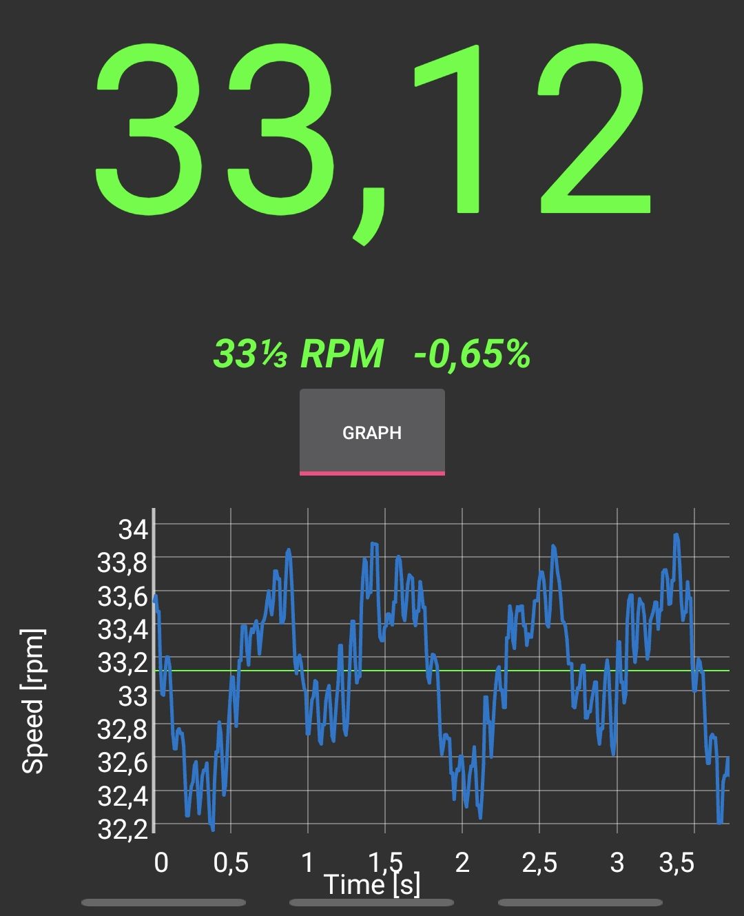
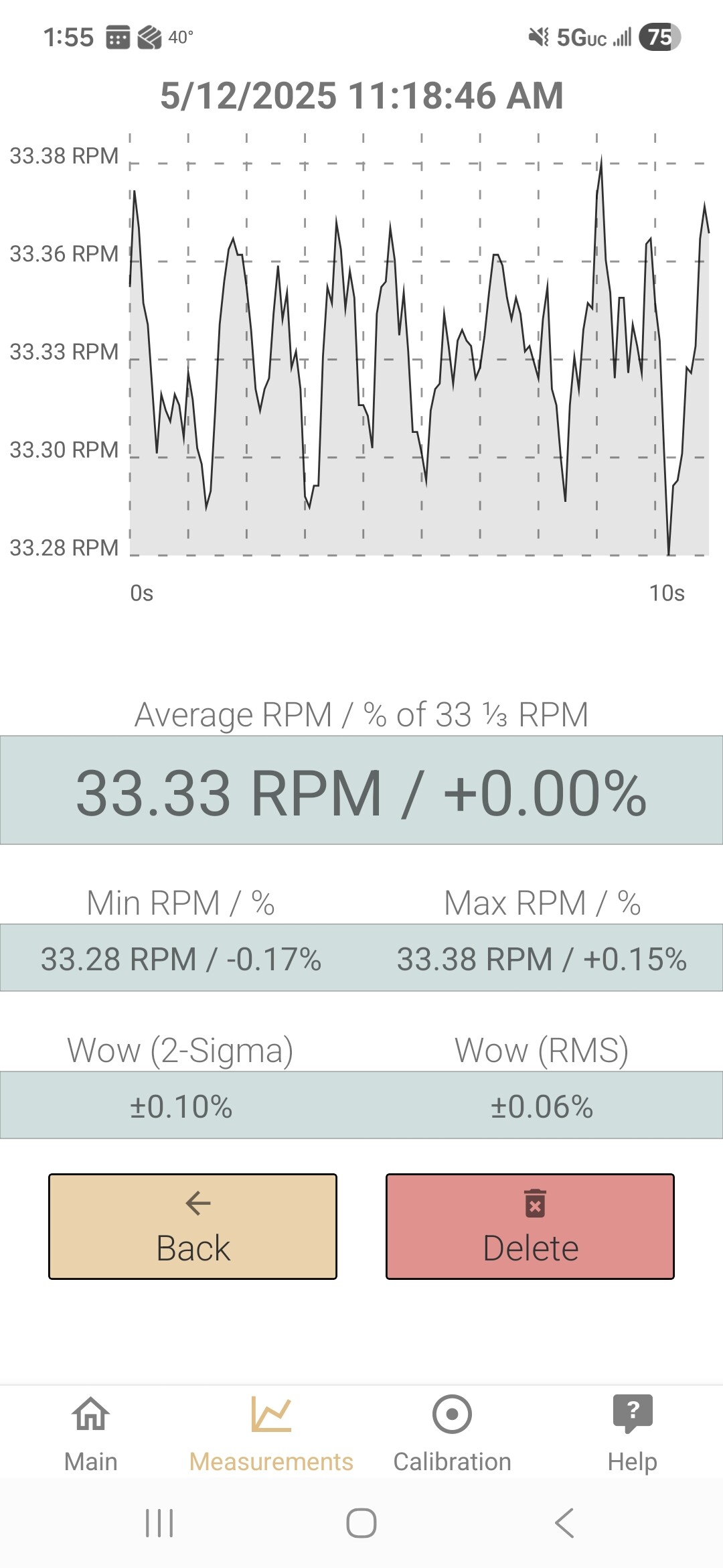
The more I try settings, the more convoluted and unexpected behavior emerges from this contraption. From time to time, when I get overwhelmed, I nuke everything from the orbit and load a fresh sample code. Now I got this: with motion::velocity and torque::voltage, my motor never gets to the setpoint (velocity is measured on my phone at around 30rpm instead of 33). However, when I downsampled motion by 10, it behaves OK (by that I mean, it floats around setpoint by ~2,5%). The same effect I got when I inserted some Serial.println, that was spamming some variable in the loop() (which, as I measured it with commander (MTT), resulted in around 250us of motion loop time - instead of 58us while containing no println or downsample). I am really curious if these numbers even make any sense, and if so, what can be a cause to such behavior?

Last thing I encountered (it’s a lot, I know) when trying to test things from the ground up; I cannot perform pole pair counting sample. For some reason, in the while loop, where motor should go in small steps in angle_openloop mode, it never even budges while the setpoint angle increases, resulting in 0 angle difference and inf PP error. I do have some mismatch in sensor direction, as I have to set negative velocity to get clockwise (or turntable-wise) direction, it might be part of reason why this doesn’t work, but I have no idea where to change that in software (if possible; I could maybe turn sensor board around, but I don’t know whether this affects it. I tried to turn a magnet around, but it seemingly didn’t make a difference).

@Rosewill2, I did perform a fair bit of experimenting with all PID variables. Turning LPF_velocity.Tf a bit up resulted in damping smallest oscillations (I could even call them ‘audible whine’), but too much resulted in unstable motion. I don’t think this setting could help with my oscillations, which have period of roughly 1Hz.

my most current code

Hey @zaguoba,

Did you try calibrated sensor from the drivers folder. It can be that at such a low speed the magnet misalignment is causing the oscillations.

Use exclusively voltage control from now on, if the current is noisy that’s gonna influence the results a lot.

I’ve tried it right now. I generated and saved the LUT and when I first ran it after I was shocked with results (I’m talking +/-0.3% oscillations, when previously I could’ve achive around +/-1% at best), but after I attempted to incorporate these results into my control code, effect kinda disappeared somewhere.

Could I get a bit of explanation what is going on with this sensor calibration and why exactly could this improve motion control? I didn’t find where this topic is covered by documentation.

The angle reported by the sensor with a “slightly” missaligned magnet has a predictable error. So e.g. the retuned angle at 10deg is actualy 11deg and at 100deg reported it is actualy 99deg. The calibration Sensor can measure with driving the Motor in open loop and remove afterwards when doing foc

1 Like

I do have a profound question. Is my idea of this solution even viable? Can I realistically expect this code to reliably drive motor at +/-.1% of setpoint or near that? I know this is a lot to ask from a free library, but it might just not be a right tool for this task (by that I mean controlling motor velocity woth exxxxtra smooooothness)

Couple of fundamental questions to consider:
Do you have a sense of the mismatch between the motor rotational inertia and the loads rotational inertia?
What is your drive train? ( Direct, smooth belts, toothed belt, etc )
What is your encoder resolution?

In my pursuit of similarly smooth motion, I have found limiting the inertial mismatch to be critical to smooth motion

So this is a tough question.
But in general it’ll be hard to get such a good velocity following without designing the whole system for this specific application.

It is hard to get such a smooth velocity from a direct drive system, would it be possible to add a reduction of some kind. Some belt drive reduction of 5-10? That would bring you right to spec and should not take too much space.

Something else to try

At the beginning of SimpleFOC I’ve actually been working with someone who wanted to create an extra smooth camera gimbal for wedding photography and needed very very low speeds, under 10rpm. And the smoothness was the key.

We were able to get some very good initial results, we did not finish the project though. However, the results were apparently much better than the ones he was able to get with an odrive (I have not really tried to do so myself though). Odrive was not designed for gimbal motors (at least not at the time 7 years ago).

The first release of the library even had the velocity_ultra_slow motion control mode. Here is the link if you wanna take a look in the docs.

Basically the idea was that instead controlling the velocity we control the position. The velocity measurement is noisy and instead of deriving the position sensor angle into the velocity we integrate the target velocity into the target angle. This ideally makes for a bit more stable system as we can remove one noise source.

The code was very simple too, you could try it if you have time. For example by using the custom control mode

// helper variable for storing last target position value
float target_angle = 0;
// position based velocity control
float custom_motion_control(FOCMotor& motor) {

  // measure the time from the last call
  uint32_t timestamp_now = micros();
  dt = (timestamp_now - timestamp_prev) * 1e-6f;
  // quick fix for strange cases (micros overflow)
  if(dt <= 0 || dt > 0.5f) dt = 1e-3f;
  timestamp_prev = timestamp_now;
  
  // calculate the target angle
  float angle = motor->shaft_angle; 
  // angle_tar = angle_cur + velocity_tar * dt
  target_angle = target_angle + dt*motor->target; 

  // calculate the target voltage
  float target_voltage = P_angle(target_angle - motor->shaft_angle);

  // return the target voltage
  return target_voltage; 
}

Then you can enable it by linking this function to the motor and enabling custom control mode.


void setup(){
...
// set the control loop type to be used
motor.controller = MotionControlType::custom;
// use voltage control for more smoothness
motor.torque_controller = TorqueControlType::voltage; 
...
motor.linkCustomMotionControl(custom_motion_control);
...
}

Make sure to tune your angle PID well though.

I have a turntable running SimpleFOC. Great performance, very stable speed control.

I use the following motor. low pole count, but cog free.

I tried higher pole gimbals, but found similar issues with cogging.

1 Like

also, connect with Jazzboy on here. He also has built a direct drive driven gimbal motor turntable.

Here is his youtube showing his creations:
https://m.youtube.com/@jazzboy/shorts