Good ideas.
Another relatively robust way would be to use bicycle discs and brake pads. (..thinking of what’s the easiest to build).
Obviously, all these reactive Dyno solutions that rely on double derivative calculation ultimately may be terrible for torque ripple analysis, due to any noise - as you said.
However, I figured we could directly measure the ripple if we attach the load cell to the motor chassis and allow the motor to rotate (within narrow limits obviously).
Unlike other solutions, this could be used to measure cogging and torque ripple under braking - by back-driving the rotor by hand or other means.
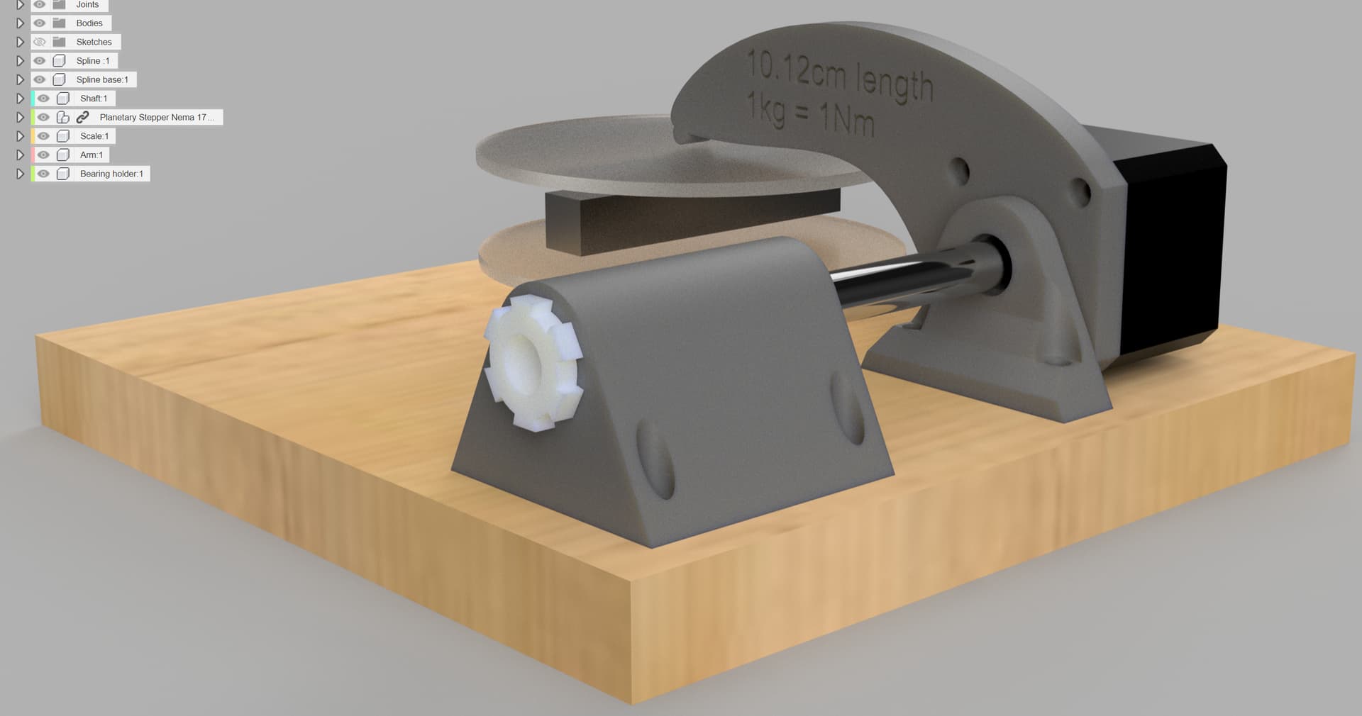
In this configuration, if the chassis moment of inertia equals the rotor moment of inertia, then the measured torque ripple on the chassis should be multiplied x2 to get the actual value of the ripple as if the motor was fixed. If the rotor moment of inertia was increased substantially, we would get more precision on the load cell and the measured value would be close to the actual value.
Comparing this against speed derivative calculations could still be done, but my guess is that it would only show how much the noise derivative method is.
One issue here is the relatively low sampling rate of the load cell (usually tops up at 80Hz). Fine for low speed. Also, since it’s basically a stiff spring, I wonder where is its resonant frequency…
At higher speeds, one may prefer to use a gyroscope or a microphone.
Just throwing another thing out there, (but it’s too complex for my need) - some people may actually want to use inline torque sensors - ones from e-bikes are relatively cheap. They could be enough for low-accuracy measurements. Or make one like this (very interesting design).
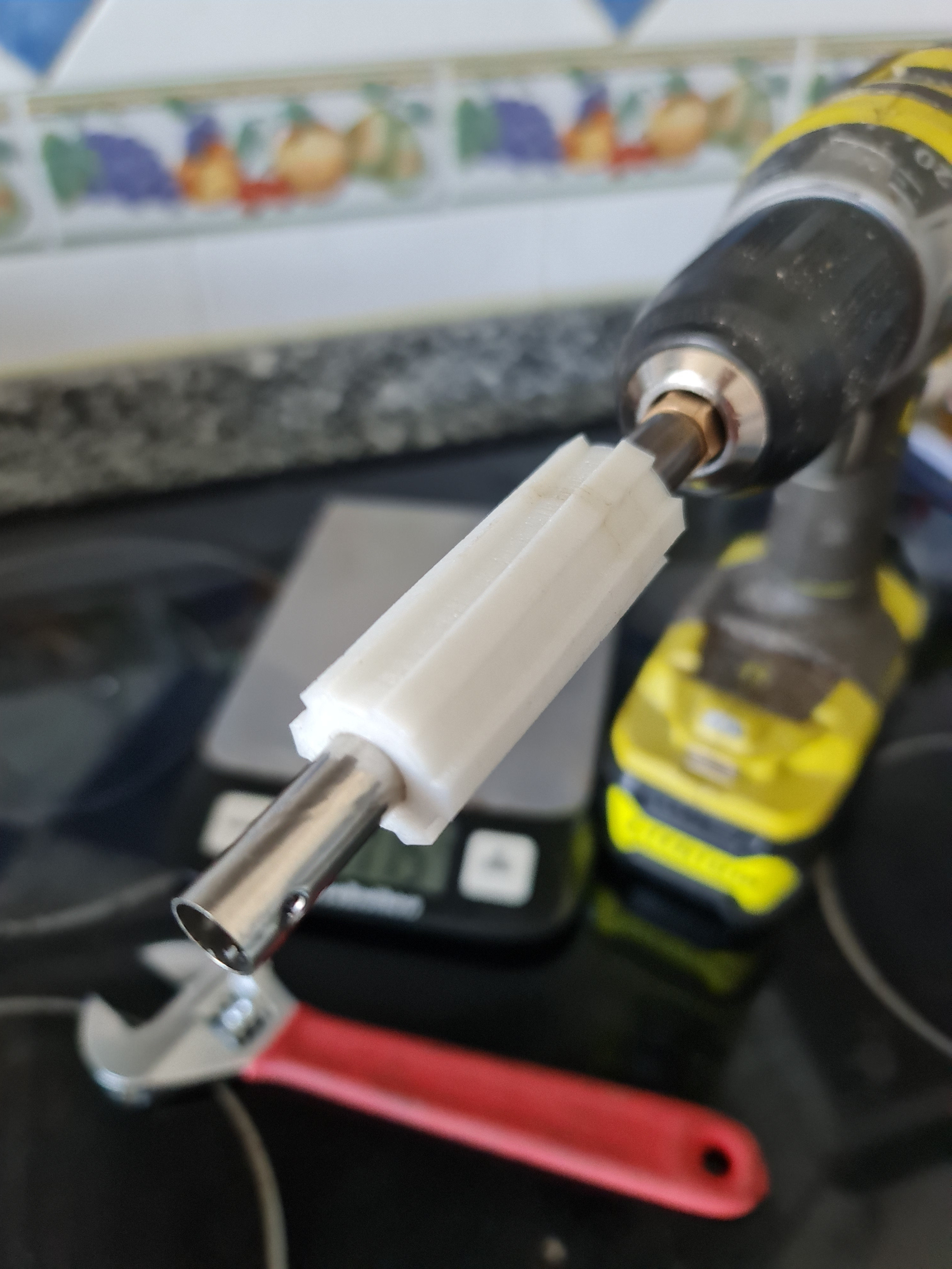
I couldn’t resist and I started building a dyno with a 6cm long and 10mm internal diameter TPU friction brake and inital test with a drill showed it was easily producing 0.5Nm of smooth torque without damage due to heat.