I also have the problem that my motor (IFlight iPower GM2804H-100T GM2804 2804) does not run completely clean. Do you think the JD-power DC-3514C runs better or smoother?
That’s not a valid question/one I can answer. It does not depend that much on the motor. As I said, the motor I mentioned has lower cogging than most motors. That is all I can tell you.
Forward / reverse dynamics could come into play from magnetic hysteresis - this is still symmetrical, just direction dependant.
If there is something else truly asymmetrical, I would speculate it would be for motors with skewed slots.
There is many things that could be done but I like simplicity of shaping the sine waveform. Though yes the effectiveness of shaping third harmonic was about 20% (maybe 30%) of torque ripple reduction at best - measured with my hand (low speed, high torque). It was very dependant on stepper too (even though their build looked the same).
Hey, why do you think torque ripple compensation should be speed dependant?
For sure it was is current dependant - at very least because of magnetic saturation / nonlinearity.
Interesting idea with the disc mass + encoder. The issue is that the mass would also “dampen” the torque ripple. But you still have to have a way to provide load to maintain certain speed. - Earlier I was thinking of attaching a cooper disk and use electromagnet and Eddy current effect to brake it. Then the brake force to the chassis could be measured with a load cell and multiplied by the radius to get the load torque. Since this wouldn’t measure only the load torque, the encoder still sould be used to get inertial torque and total instantaneous motor torque.
I think it would depend on speed due to the (rotational) inertial mass - if you’re going fast, your mass carries you through the cogging events with less perturbation.
But I would expect this can be accounted for using maths, and not needing different LUTs for different speeds.
I have to think about that one ![]()
It certainly sounds like a cool thing to set up and see what results one gets!
Ah, but that’s equally valid for the compensation action - the waveform sweeps so fast that small changes in it’s shape become negligible. To the point that you could even apply square wave and it would be somewhat smooth at high speed.
Btw, seems that Eddy current brake is a common thing for dynos Eddy current brake - Wikipedia.
The coils could be built using PCB traces: GitHub - atomic14/kicad-coil-plugins: Some simple plugins for generating stator coils in kicad
The only problem for me is that it wouldn’t work for hight torque at low speed.
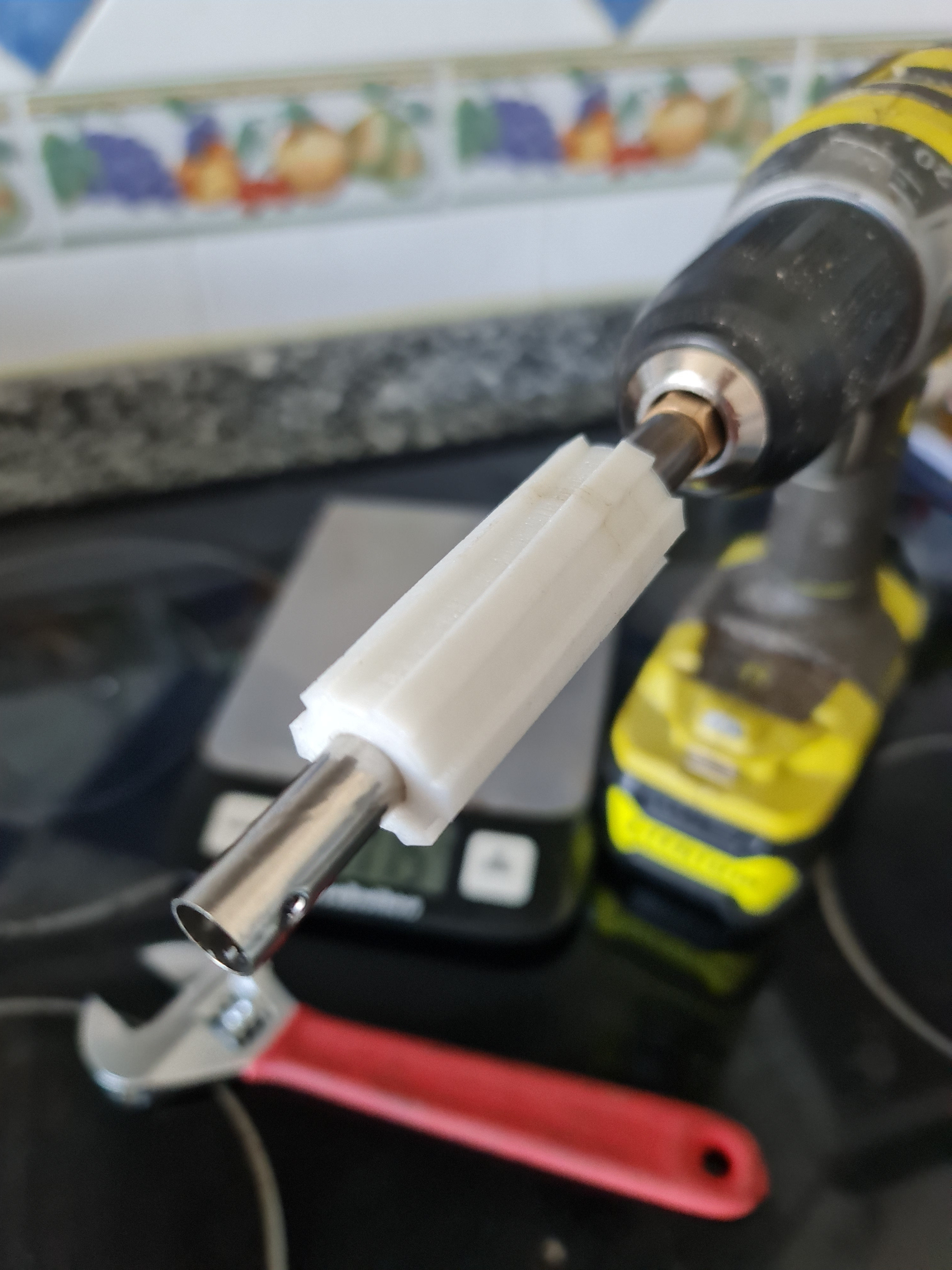
Actually, I think I will end up with much simpler TPU friction brake. I know it works pretty well because I had a little 3D printed TPU bead that was sliding on the shaft. I just need to make it much longer and optionally attach to load cell.
@Anthony_Douglas Low inertia of the Dyno will be critical to see the torque ripple with good precision. The motor inertia can be measured if needed. But really absolute torque values are not important to see if the ripple was reduced.
I was just thinking any waveform modification of the voltage wave or PWM wave would work best at a certain speed, and not as well at other speeds, due to the impact of inductance and other time dependent phenomena that impact current flow and the amount of torque experienced at any given moment. I don’t know how large the effect would be though.
I was investigating various methods of braking for a centrifuge project I was working on a ways back and I like the idea of using eddy currents like that, I think it would be very smooth and thus interfere minimally with other stuff. And an aluminum disk can be used. I might just use an RC servo motor with a magnet on it on a lever if it was me. Just a handy but fairly repeatable way to move the magnet closer/further away.
But actually for measuring torque ripple here I would try to measure the variation in velocity of the disk and take the derivative of that. It wouldn’t give you an absolute value for the torque but I think it would be easier and pretty sensitive. A lighter disk would allow more sensitivity but also allow more noise due to air whipping around and whatever.
I think if you used rare earth magnets and a disk of large diameter made of say half inch aluminum that could give pretty good torque at fairly low speeds, kind of vague, I’m sure there is some way to calculate this.
Another approach could be to use compressed air blowing on the disk maybe? Like a tesla turbine. A normal turbine would introduce torque ripple of it’s own :(. You can regulate flow from an air compressor fairly nicely using the regulator. You just turn the knob on the regulator to increase flow.
1 Like
Good ideas.
Another relatively robust way would be to use bicycle discs and brake pads. (…thinking of what’s the easiest to build).
Obviously, all these reactive Dyno solutions that rely on double derivative calculation ultimately may be terrible for torque ripple analysis, due to any noise - as you said.
However, I figured we could directly measure the ripple if we attach the load cell to the motor chassis and allow the motor to rotate (within narrow limits obviously).
Unlike other solutions, this could be used to measure cogging and torque ripple under braking - by back-driving the rotor by hand or other means.
In this configuration, if the chassis moment of inertia equals the rotor moment of inertia, then the measured torque ripple on the chassis should be multiplied x2 to get the actual value of the ripple as if the motor was fixed. If the rotor moment of inertia was increased substantially, we would get more precision on the load cell and the measured value would be close to the actual value.
Comparing this against speed derivative calculations could still be done, but my guess is that it would only show how much the noise derivative method is.
One issue here is the relatively low sampling rate of the load cell (usually tops up at 80Hz). Fine for low speed. Also, since it’s basically a stiff spring, I wonder where is its resonant frequency…
At higher speeds, one may prefer to use a gyroscope or a microphone.
Just throwing another thing out there, (but it’s too complex for my need) - some people may actually want to use inline torque sensors - ones from e-bikes are relatively cheap. They could be enough for low-accuracy measurements. Or make one like this (very interesting design).
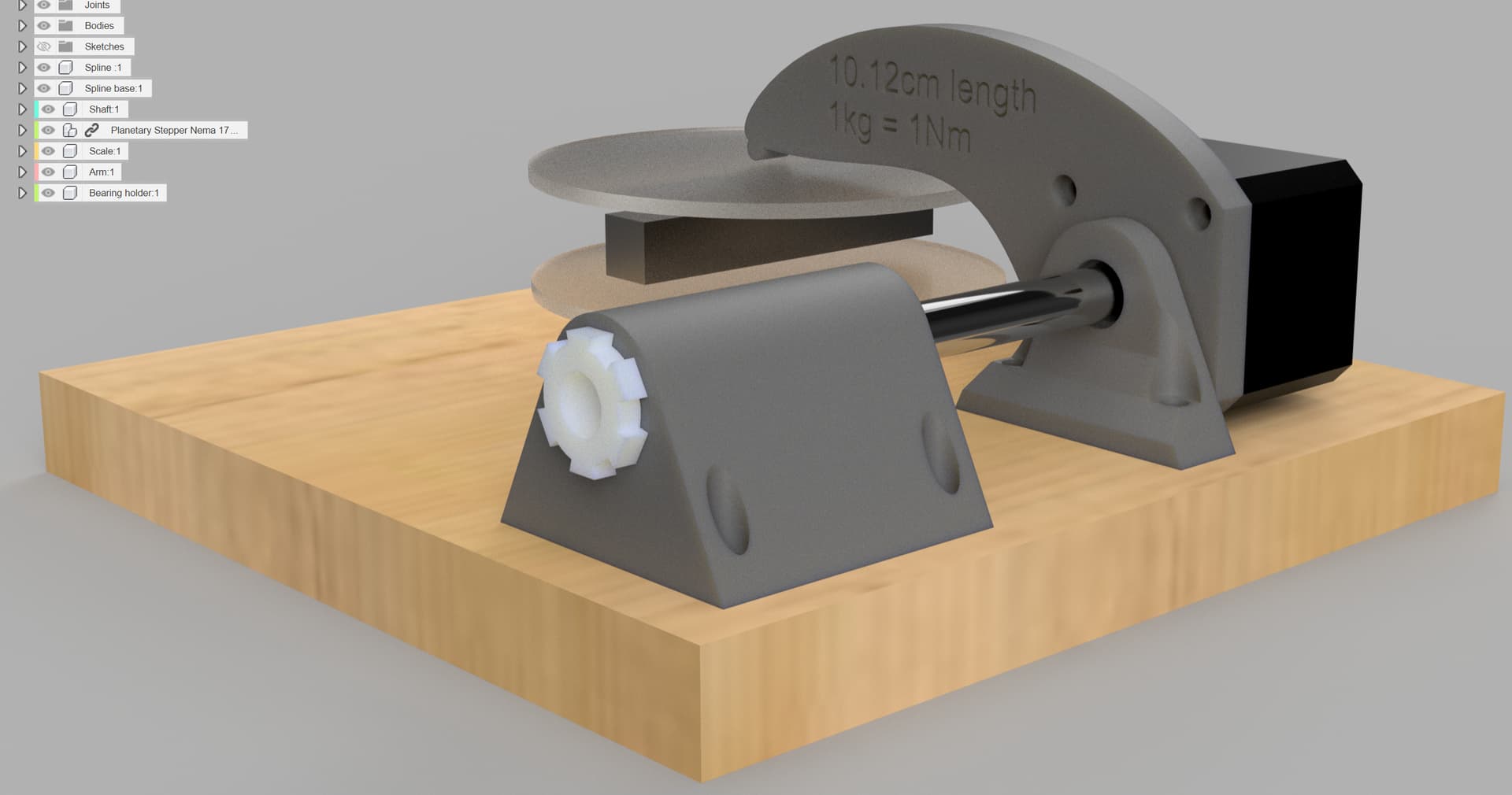
I couldn’t resist and I started building a dyno with a 6cm long and 10mm internal diameter TPU friction brake and inital test with a drill showed it was easily producing 0.5Nm of smooth torque without damage due to heat.