Open Loop test with ESP32

Hi all,

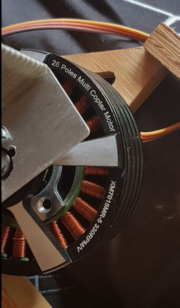
Here is my first test of this great library. Open loop mode with ESP32 and a quite big Gimbal BLDC 24 poles motor.

See the result here :

As you can see I feed the motor with 2A 12V

code is a merge of examples from the lib :

/**
 * ESP32 open loop control example sensorless 
 */
#include <SimpleFOC.h>

float target_velocity = 0; // rad/s

// Motor instance
//  BLDCMotor( pin_pwmA, pin_pwmB, pin_pwmC, pole_pairs, enable (optional))
BLDCMotor motor = BLDCMotor(25, 26, 27, 12);

void setup() {


  // power supply voltage
  // default 12V
  motor.voltage_power_supply = 12;
  
  // choose FOC modulation (optional)
  motor.foc_modulation = FOCModulationType::SpaceVectorPWM;

  // set motion control loop to be used
  motor.controller = ControlType::velocity_openloop;


  // contoller configuration 
  // default parameters in defaults.h

  
  // maximal voltage to be set to the motor
  motor.voltage_limit = 7;
  motor.velocity_limit = 50;

  // use monitoring with serial 
  Serial.begin(115200);
  // comment out if not needed
  motor.useMonitoring(Serial);

  
  // initialize motor
  motor.init();


  Serial.println("Motor ready.");
  Serial.println("Set the target velocity using serial terminal:");
  _delay(1000);
}

void loop() {
  // open loop velocity movement 
  // using motor.voltage_limit and motor.velocity_limit
  motor.move(target_velocity);

  // receive the used commands from serial
  serialReceiveUserCommand();
}

// utility function enabling serial communication with the user to set the target values
// this function can be implemented in serialEvent function as well
void serialReceiveUserCommand() {
  
  // a string to hold incoming data
  static String received_chars;
  
  while (Serial.available()) {
    // get the new byte:
    char inChar = (char)Serial.read();
    // add it to the string buffer:
    received_chars += inChar;
    // end of user input
    if (inChar == '\n') {
      
      // change the motor target
      target_velocity = received_chars.toFloat();
      Serial.print("Target velocity ");
      Serial.println(target_velocity);
      
      // reset the command buffer 
      received_chars = "";
    }
  }
}

It works really well, but as it is in open loop the motor ends by loosing the sync and stalls.
I can’t bear waiting for my magnetic sensor to come from China…
I would be really interested in helping if current sensing mode would be developped.

Thanks for all teh efforts done in this lib

JP

1 Like

Nice video.

I agree, it is unintuitive that the current drops when speed gets faster. I’m guessing the increasing back emf is cancelling out voltage supplied.

Have you tried ā€˜motor.controller = ControlType::SpaceVectorPWM’? I believe that control type is supposed to better model bemf and might yield some minor motor control improvements (speed/power/smoothness??).

Do you have a link to the motor you use?

I think current sensing is interesting too. It can be used for 1. torque control (just average current needed) and 2. ā€˜sensorless’ measurement of angle + possibility of matching voltage to bemf shape.

thanks for the ā€œ```ā€ tip → much nicer !

I don’t have a real link for the motor it seems to be a quadcopter which was rewinded as a gimbal one
It’s a dualsky one www.dualsky.com. I got it more than 8 years ago at the very very begining of gimbals.

But even the number of poles is not good… said to be 28, but I can only count 24 coils…
I have measured 5 Ohm per coil

seems that the closest one nowadays is this one : Xmotor Brushless Gimbal Outrunner

I just tried but got this error :

'SpaceVectorPWM' is not a member of 'ControlType'

But as I already had these lines isn’t it the same ?

// choose FOC modulation (optional)
  motor.foc_modulation = FOCModulationType::SpaceVectorPWM;

Yes ! and exactly what I would like to do for my ebike controler :slight_smile:
I am also tempted by regenerative braking, but I haven’t found too much on internet for this…

:blush: I meant:

motor.foc_modulation = FOCModulationType::SpaceVectorPWM;
1 Like

I think that is a 24n28p motor. I.e 24 slots (coils) and 28 poles (magnets). If so your constructor should be

ā€˜BLDCMotor motor = BLDCMotor(25, 26, 27, 14); //14 pole pairsā€˜

Don’t think it matters too much in openloop - apart from perhaps your real speed is a little lower than you asked for.

Thanks @Owen_Williams.
I counted the coils thinking they were poles…
Still a lot to learn with motors…

Hey @freedom2000,
I like your video and the setup. Its cool how you added the heatsinks. I never tried to do so, but this should help a lot!

Rgerding the question about the less current for higher velocities:
When you are running the open loop you are applying the same voltage V = motor.voltage_limit the whole time. During the stall (target_velocity = 0) and for any other target_velocity value.

Now the electrical current of the dc motor (the same is true for the BLDC when you are in the clarke+park transformed d-q frame):

current = (voltage  - Bemf)/R = (voltage - k*velocity)/ R

where voltage is applied voltage, R is the motor resistance, current is the achieved current, Bemf is the the generated Back EMF voltage which is proportional to the motor velocity and a motor back emf constant k.
So as you can see from equation as velocity grows and voltage stays fixed, your current will decrease.

I am really interested to see your setup once you receive the position sensor, you will see that your motor will have much more torque and it will use much less current!

Thanks @Antun_Skuric for this explaination.

It’s clear now why the current is dropping while the BEMF (velocity) increases.
BTW, wouldn’t it be an idea to increase the motor.votage.limit to balance this electronics normal behavior ?
I mean a kind of proportionnal increase of this value with the velocity (in open loop mode of course)

current = (motor.voltage.limit * (1+ k.velocity) - Bemf)/R = (voltage + k.velocity - k.velocity)/ R

I will have to wait 2 weeks before getting the mag sensor. But for sure I will do a new video.

Regarding the heatsink, it is indeed very efficient (altough not the best place for a heatsink…). I can now sustain 2A into the coils without burning my fingers :slight_smile:
I also have a big copper pad under the chip which is also getting really hot.
And I could as well add a fan on this dirty CPU heatsink !

Right now, before getting the mag sensor, I will try to add an IMU to this and re activate my gimbal which has been sleeping since 2013…

JP

Yeas you could definitely do something like that. Change the voltage limit proportional to the velocity you are in. This would enable you to reach higher velocities as well.

You could also maybe do current limiting control by estimating the current based on the equation above. You already have the resistance value, you only need to know the K of the back-emf. But this should be easy to calculate or even find experimentally. :smiley:

Then you could do something like this:

motor.volatge_limit = target_current*R  + K*target_velocity;

This could be a cool experiment. Then your stall current will drop to the desired value target_current and it should stay more or less constant for any target_velocity.

2 Likes

thanks a lot for these posts! I am not that good at these things and don’t have much time or money, so it might not seem to you like you are sharing much, but it is very valuable. The documentation of this project, like many open source projects, is not very good. I could find nothing on the main page about running a motor open loop.

I am building an open source energy recovery ventilator, and I require some quiet motors. This has turned out to be very hard to accomplish. I may have to turn to FOV. However, even that may not be sufficient, I can hear in your video that there is quite a lot of noise, some kind of humming noise. The PWM frequency of the library is I think 32 khz, which should be inaudible. However maybe you have adjusted that, or something?

I need about 3000 rpm, about 3 watts per motor of actual mechanical output, so I figure 6 watts or so of input, depending on their efficiency at the rpm they end up operating at etc. I have ordered some gimbal motors, small ones 32 mm or so in diameter, which I hope will be sufficient. They are suitable KV rating. I hope to use 12 volts.

I need it to be inexpensive, these boards are mostly too expensive. I might be able to use 3 half bridges that I get for relatively cheap, probably by buying 2 full hbridge boards (or chips). My power requirements are not that strict.

If this doesn’t work, I might have to resort to using a DAC and op amps. However that might be too expensive.

I have tried using some of the little ESC usually used in models, but they still make noise. They make the chopping frequency 16khz, which is just not high enough. Some people can hear that, some people can’t. It is idiotic that they picked that frequency, thinking it is inaudible. A lot of people can totally hear that.

I need resistance to oscillations in the shaft, which FOV can give, because the motor of course resists increases and decreases in angular position, but precise RPM isn’t actually important.

I am using it to drive the vanes of a roots blower. Each vane will get it’s own motor, and also there are ā€œbackup gearsā€ which have a large backlash i.e. a large spacing, about half a mm, between the opposing gear’s teeth. They don’t engage normally, but if one vane gets too far out of position relative to where it is supposed to be, the gears engage. There is a photointerrupter which is broken by the teeth of the gears. That allows me to determine the relative position of the vanes to some degree, and adjust their position in software, when things are rotating.

The whole thing is pretty price sensitive, so I am having a real hard time. There is no way I can afford encoders at $15 each for the cheapest ones. That would be $60 just for the encoders. The whole unit has to sell for like $500 or less.

Welcome, @Anthony_Douglas ,

Sounds like an interesting project! A few comments:

  • I can confirm that gimbal motors can be driven completely silently. But only at low RPM. At 3000RPM you might be able to achieve quiet operation, but not silent.
  • At low loads, the efficiency gains of FOC compared to open loop are large. So 3W output might be more than 6W input in open loop, but less when you use closed loop.
  • Depending on the MCU, the PWM frequency can be set quite high, and definately in the inaudible range.
  • Cheap ESCs don’t use fast MCUs, and don’t use FOC capable drivers. They do this to save costs, and simplify the software. That’s why their PWM frequencies might be lower, and why they don’t support sensors.
  • Using FOC, you need a precise sensor. Unfortunately, this is an expensive component.
  • You don’t say how many motors you need?

Have you try motor.foc_modulation = FOCModulationType::SpaceVectorPWM; ?