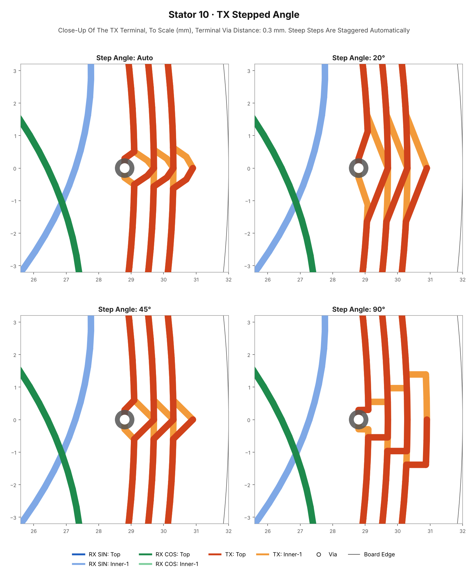
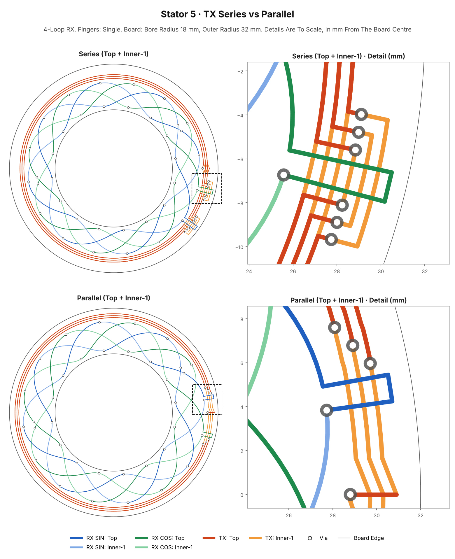
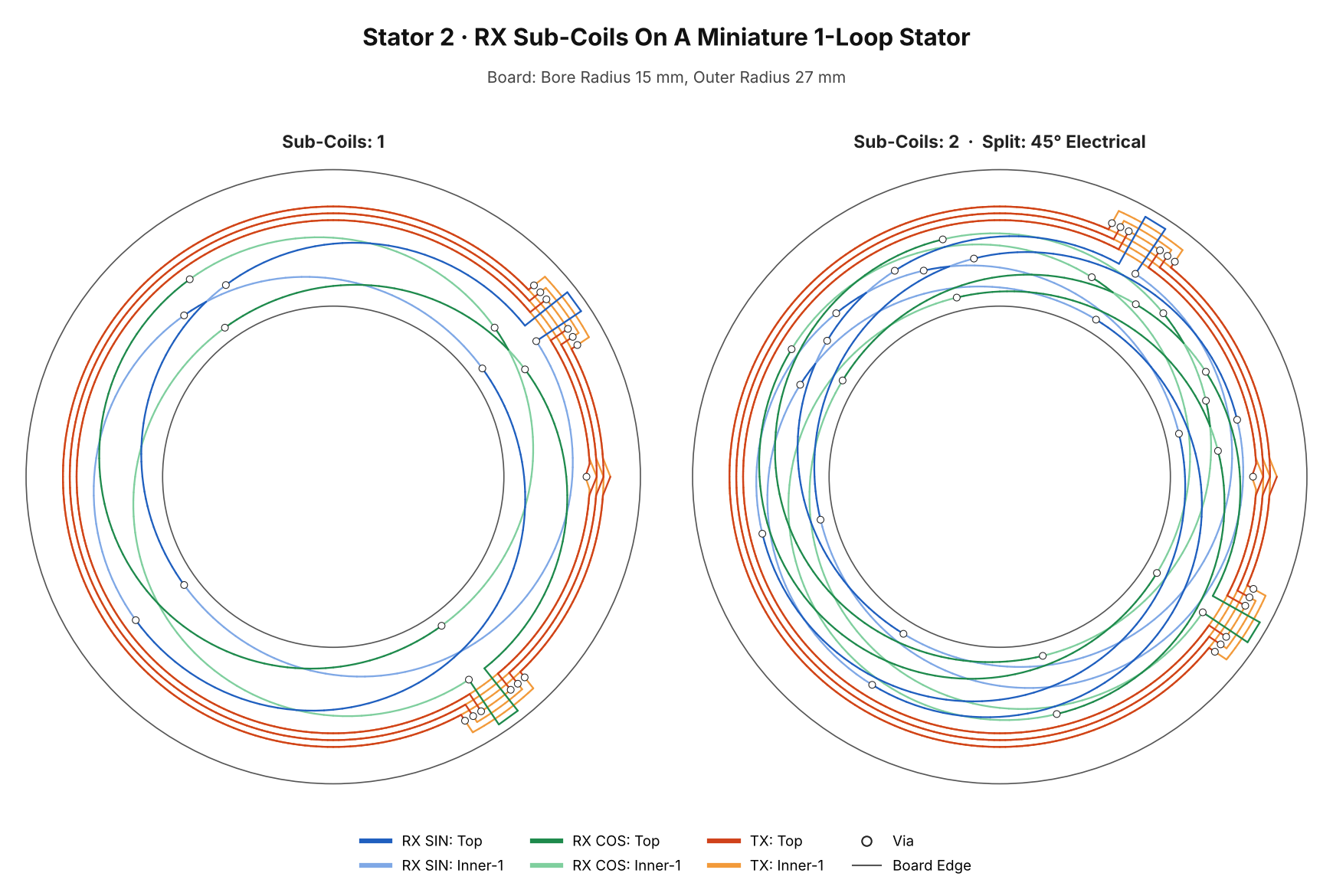
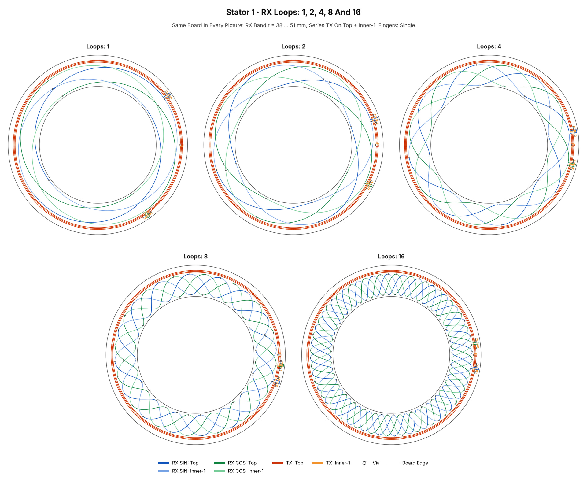
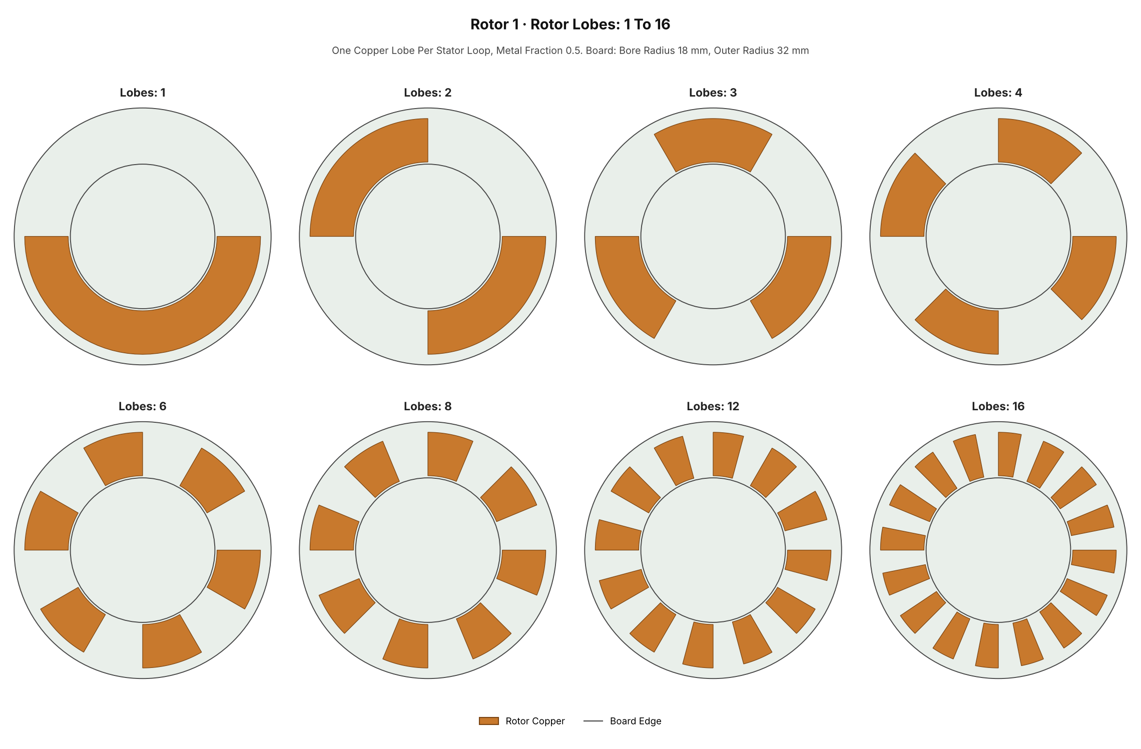
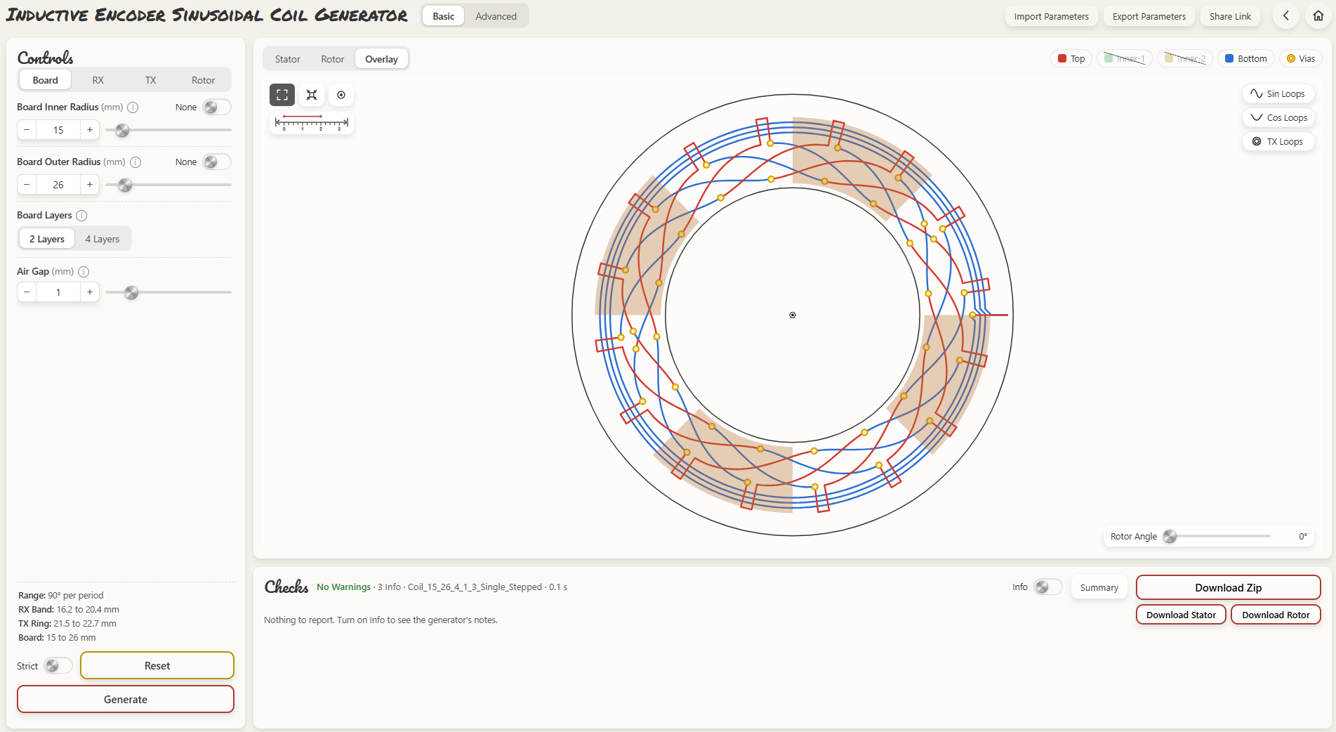
Over the last three months I have been building a tool for something I kept wanting in my own robots: a high-resolution, absolute angle sensor that does not cost hundreds of dollars. The result is the Sinusoidal Coil Generator, a Python program that writes complete KiCad boards for the stator and the rotor of a rotary inductive encoder.
How the sensor works
A transmitter coil on the stator PCB is driven at a few MHz by a receiver IC such as the Renesas IPS2200 or IPS2550. A rotor PCB with copper lobes turns in front of it. Two sinusoidal receiver coils pick up a SIN and a COS signal that follow the rotor angle, and the angle is atan2(SIN, COS). There is no magnet and no optics, and the whole sensor is two PCBs.
What the generator does
1 to 16 electrical periods per turn. One loop gives a true absolute 0–360° sensor. More loops give finer resolution, and matching the loop count to the motor’s pole pairs lines the sensor up with commutation.
Builds the receiver coils (three profiles, optional sub-coils), the transmitter coil (series or parallel, stepped or spiral) and the matching rotor.
2- or 4-layer boards with through vias only, so any low-cost PCB fab can make them. The smallest 1-loop board that passes every check has a 12 mm outer radius.
Checks every parameter and the finished geometry, and estimates TX inductance, tank capacitors, oscillator frequency and RX voltage against the IC limits.
An optional analyser and optimizer model the copper in 3D and report the angle error over a range of air gap, eccentricity and tilt.
Output opens in KiCad 7, 8, 9 and 10. No libraries or footprints needed.
Where SimpleFOC comes in
The IPS2200 gives analog SIN and COS outputs, so it should work with the LinearHall class in the drivers repo, or with GenericSensor and your own atan2. I have not tried this yet. If you have run an analog SIN/COS sensor with SimpleFOC, I would really like to hear how it went.
My hope is that SimpleFOC systems will be able to use high-resolution inductive encoders on the go: generate the coils for your motor, order two PCBs, and connect them like any other sensor.
Honest status
No hardware has been measured yet. The first test boards are ordered, and every number in the repository is a model estimate until they are measured.
The code is free to use, study and change for personal, educational, research and hobby use (PolyForm Noncommercial 1.0.0). Commercial use needs written permission.
What would help
Measurements, if you build a board: inductance, oscillator frequency, signal amplitude, angle error.
Feedback on the coil geometry from anyone who has designed inductive sensors before.
Advice on reading the SIN/COS signals cleanly on an STM32 or ESP32 alongside SimpleFOC.
Thanks for reading. I am happy to answer questions here.
Interesting project! Especially nice that the center of the coil is hollow, so it doesn’t need access to the end of the shaft like a magnetic encoder.
LinearHall will indeed work for it, although you may want to override _atan2 with a higher precision function instead of the fast approximate we use
STM32 has the best ADC. You can see one of my custom setups for it here (functions initADC, setChannelEnabled, getResult)
Injected channels on both ADCs are used for current sense, ADC1 regular mode reads the internal temperature sensor, and ADC2 is used for general purpose including linear halls. It’s set up for 4x hardware oversampling, but actual oversampling is higher (up to 128x). It reads into a circular DMA buffer (dynamically sized so the oldest entries are <47µs old), and then the getResult function sums up all the entries for the requested channel.
But for low-cost resolution, MT6835 is hard to beat. Under $6/pc on amazon including the magnet, and can be configured to give a stable 18-bit reading at low speed. For higher speed, it’s 15 or 16 bits stable. You need to run it through CalibratedSensor for nonlinearity, but these inductive sensors may need that too. We’ll have to wait and see your testing results. You could use the calibrated MT6835 reading as a reference to compare yours against. It will be most accurate with a stepper motor, which has a large number of precise positions it can move to for calibration.
Thanks for the reply. I am currently planning on going with Renesas IPS2550. Plan is to make around 16 maybe 32 boards of different settings and get real world data on 16 bit resolution, 18 bit resolution and 21 bit resolution. The accuracy is what intrigues me with these chips.
For the MCU I will go with stm32g4 series since I have quite a lot of them lying around.
For the motor I will go with the T - Motor GB series(Already have a bunch lying around) or CubeMars Gimbal series. Depends on whatever is left of my budget by the time the electronics arrive. And now I have included some steppers(Most likely some NEMA23s as I may use them to make a table lifter later) after your comment above.
For the test bench bearings I am going with NTN Japanese bearings 6800 series since I already know the jitter and have their exact preload data configured somewhere in my projects folder.
Thanks for the pointer. I will most certainly do this. I want to make a fully industrial solution for everyone. As my budget rises i will invest in some cobot motors as well.
Yes I wanted to make the inductive sensors for humanoids and apparantly Renesas didnt want to give me permission to use their tool so I made their industrial tool from scratch to replicate what some of the very popular german encoding companies do.
Yes at first I will test with the STM32 ADC and then switch to a 21 bit ADC. I am currently making the generator produce coils for low RPM extremely high percision usage. My later prioroty would be to focus on the higher speed stable percision applications.+ I will be uploading all the super optimized boards on the GitHub which will be rigorously tested over the next 6 months.
What you described is a bit over my head, I must admit.
But common sense with inductive proximity sensors is, that they are quite temperature sensitive.
And they should be mounted with no metal nearby.
I hope those restrictions don’t apply to your setup.
Hello, The temperature is not at all a factor in consideration. Rotary inductive sensors are quite immune to them. The problem however is the stray metal and poorly planned all metal setups. With a two pcb setup and around 1mm air gap, the problem ceases to exist if the surrondings are planned to have either plastic housing or accurately placed thick pcbs.
I will elaborate on this in some super optimized examples that i come up with in the future.