I did that today and the motor doesn’t initialize, BUT instead it jumps to zero everytime I restart it. That’s a bit like the proverbal pest vs cholera thing.
How can I change the initialisation in such way, that motor & sensor are aligned, but doesn’t move?
It’s very unlikely that the extruder motor is at zero, when I switch the printer off.
I also can’t tell it to move to zero at the end of a print. I only have the step/dir interface and no commander…
But this has to do with your target value?
I am not sure I have understood the situation 100% correctly, but if you have initialised your motor to the correct electrical zero and direction, and you now want to power it up in position mode, then it will move to the target position when you enable it and run motor.move().
So if you want to enable it, but want it to remain still, just set motor.target = sensor.getAngle(); before enabling the motor?
I’d never thought of that!
I wanted to use the EEprom flash to store the last angle, but that’s much easier.
It didn’t work out as expected, but I figured out how to include the start angle.
The answer was in the loop:
*snip*

// initialize motor
  motor.init();
  start_angle = sensor.getAngle(); 		//	Dummy variable to store initial sensor angle
  motor.target = start_angle;
// align encoder and start FOC
  motor.initFOC(4.75, Direction::CW);
// init step and dir pins
  step_dir.init();
// enable interrupts
  step_dir.enableInterrupt(onStep);
   _delay(1000);
}
void loop() {
  motor.loopFOC();
 // Motion control function
  motor.move(start_angle + step_dir.getValue());	//	adding the start angle here inits the motor without moving to zero
}
Thanks for pointing me in the right direction ![]()
Before I calibrated the sensor-alignment, I got an error message several times:
something like:
pp check failed: estimated pp = 7.83
The real PP is 7, do I have to worry about it?
I didn’t see the message after I set the calibrated sensor angle because it skips the PP test.
Yes, ideally the PP check should succeed. If it fails, the calibration isn’t quite right. On a low PP motor, and if it fails not by much, then things can still work (though usually you will then find the motor runs better in one direction than the other).
You should obtain the calibration while the motor is unloaded (no filament to pull). Then I assume it will succeed, and you can use that value.
Isn’t there a way to truncate the PP-value?
I’ve never heard of a motor with 7.8 PP…or any stator with a fraction-pole count.
Or, the calib-routine should accept the given value, when it’s close to the measured.
Well, the problem is that the motor does not have 7.8PP. It has 7. But based on the electrical zero found the sensor calibration is returning a different measured value.
This means, in the end:
- that either the PP setting is wrong (not the case)
- or the sensor isn’t working well (not the case)
- or the electrical zero was not properly found and/or the motor was not able to freely move in open loop mode during the calibration (this is presumably what is happening).
So the failed PP check is a warning to you that the calibration didn’t work well. Its not something you can just round away.
The as5048 sensor I’m using has an inbuilt gain-calibration routine. Is that something the init routine has to trigger or can we read out the magnetic strength?
I have placed sensor and magnet 1.5mm apart, which is in the middle of their recommended gap. But I might have a bad gain-setting?
I’ve never messed with this gain setting… can it even be changed?
If you use the dedicated AS5048A driver from our drivers repo you can read the magnitude to check.
1.5mm air gap seems high to me. I use more like 0.5-1mm most of the time. The magnitude reads out at 4000-4500 IIRC.
From what I learned of how these sensors work, they are not nearly that sensitive…I seriously doubt it is the magnet. Just print out the angle during the calibration routine and you will probably see something irregular. Just print print print, look into the system and try to spot what is not doing what you think it should be doing and results usually follow in my experience.
The data sheet of the sensor says, we have to add a 10uF capacitor if we don’t use the onboard LDO.
I cut a corner and used a scavenged cap from an old PCB. Maybe it’s important to have stable 3.3V…
I bought a used oscilliscope, when it arrives, I’ll take my time to tune it. (PID is a bit too soft, too)
Yes, the AS5048A is fussy regarding its power supply. For 3.3V and 5V there are different wirings, it’s shown in the Datasheet.
It’s important to get it right, or the sensor won’t work or will be unreliable
Yeah I mentioned a while back that the sensor has to be wired right depending on power supply voltage etc., that’s what I was alluding to. Also some pins need to be connected to each other or not depending on what voltage is used.
The BLDC extruder took another route. Now I have a tiny NEMA8 stepper as pacemaker on the toolhead and want to add a bigger stationary motor with constant torque setup that pushes the filament into the NEMA8.
It’s still unclear which motor type I’d use. Does sFOC work well with steppers in torque mode?
My dual H-bridge driver doesn’t have current sensing.
I also have a geared DC motor with optical encoder, but IDK how to synchronize the two motors with a step/dir interface
I’d say don’t worry about it yet. Just use any BLDC you have on hand, with a B-G431B-ESC1 or something with current sense to find out if the concept will work at all.
Best advice. Honestly I don’t think this is an advisable approach for an extruder.
What you want is basically a very low backlash stepper motor with gears. So like a harmonic gearhead, or you could use water cooling with the stepper motor and throw a ton of current at it. A small diameter pinon to drive the filament would help, the ones usually used are bigger than they need to be. Two would be even better as you could apply more force which means more printing speed. One motor, two small pinions, some well made gears with minimal backlash and ball bearings would be the way to go in many ways. Automatic backlash compensation applied whenever the motor reverses direction. Compressed air cooling for bonus points, would allow the motor to be a lot smaller without adding practically any mass. But then the cooling can fail and things go sideways, so you need a protection system and blah blah it gets expensive.
Using a stepper motor on a direct drive head is not a great idea because they are very heavy for the power they output, and it is ultimately about power output, with the desired control. But servo motors are not a great idea for an extruder because the servo error and fluctuations will affect the quality of the print. Stepper motors are cheap but they actually work pretty well when it comes to really giving the output they are commanded to. There is ringing etc. sometimes but suitably designed a stepper based system actually has many advantages over a servo motor based system, in terms of sheer performance, not just cost.
Whether it’s a stepper or a bldc, you still need gearing to get the slow high torque motion with low mass. Then backlash can be an issue, but it’s relatively minor in an extruder. Harmonic gearing would solve that, the only issue is they cost a lot and wear out.
I guess, you haven’t seen the video I linked? The VDE-100 concept comes with a unique inbuild gearing with no backlash.
The stepper already runs at 2000+steps/mm which is a much higher gear ratio, than usual geared extruders have.
The gear ratio is so high, it isn’t back driveable. So I can constantly push filament from a remote motor into the VDE-100 but the small stepper determines the amount of extrusion. It acts more like a valve than a pump…
In theory this is the best of both worlds:
- lightweight direct drive with instant retractions
- high extrusion rate like a Bowden-tube remote extruder
Steppers are actually a good fit for the particular job of an extruder. You need high torque (extrusion) and high speed/acceleration (retraction), but never at the same time so the total power output is always pretty low. This is why the NEMA14 pancake is so hard to beat. It’s 55 grams, plenty powerful, no special driver, and in larger quantities about 8 bucks plus the effort of drilling the shaft. Light enough that you’re into diminishing returns versus focusing on weight of other printhead components.
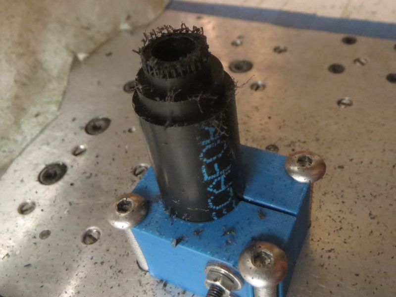
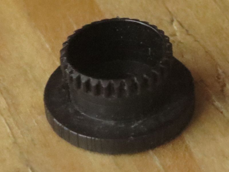
That said, it would be fun to try a micro outrunner with harmonic gear ![]() Then hall sensors would give enough resolution, eliminating one of the obstacles to using outrunners for this style of extruder. I have made harmonic gears for guitar tuners. This delrin cup is 0.28mm wall thickness, 10.5mm OD, with teeth protruding .5mm from the surface. Seems to be holding up just fine with .3Nm static torque from a guitar string for a few months, but I would want it bigger for an extruder that’s moving all the time. And make the wave generator out of 1x3x1.5mm ball bearings in an elliptical pattern to reduce friction (it’s not backdriveable with sliding contact wave generator… which is good for a guitar tuner)
Then hall sensors would give enough resolution, eliminating one of the obstacles to using outrunners for this style of extruder. I have made harmonic gears for guitar tuners. This delrin cup is 0.28mm wall thickness, 10.5mm OD, with teeth protruding .5mm from the surface. Seems to be holding up just fine with .3Nm static torque from a guitar string for a few months, but I would want it bigger for an extruder that’s moving all the time. And make the wave generator out of 1x3x1.5mm ball bearings in an elliptical pattern to reduce friction (it’s not backdriveable with sliding contact wave generator… which is good for a guitar tuner)