It’s an M4 core, so we have floating point hardware, I don’t know if double takes longer than single.
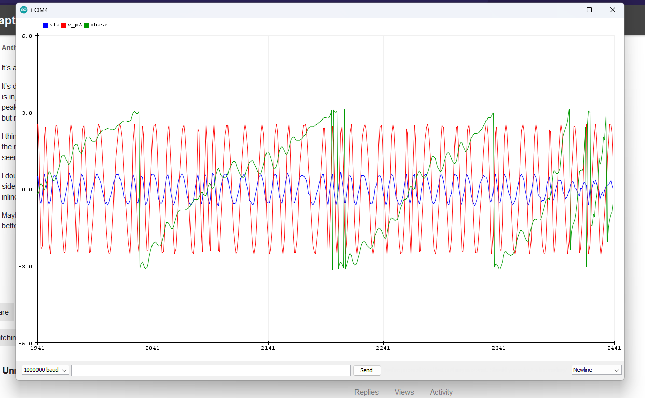
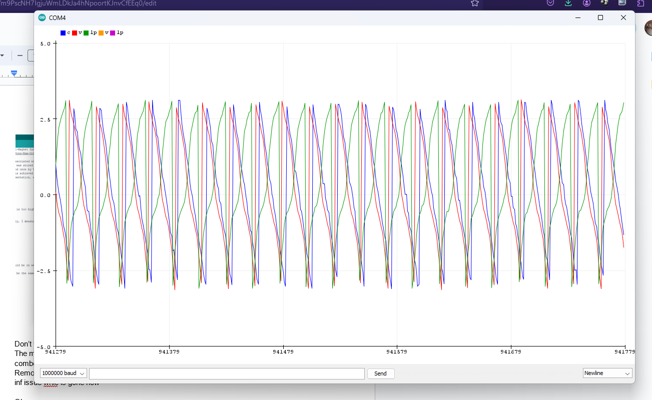
It’s doing something, but the “phase”, which is supposed to represent the position in the cycle that the rotor is in, is definitely not reading right. It oscillates around but the center of the wave drifts, and the peak to peak is not right at all. I tried observer gains from 10 to 30,000 and some will lead to various instabilities, but nothing correct.
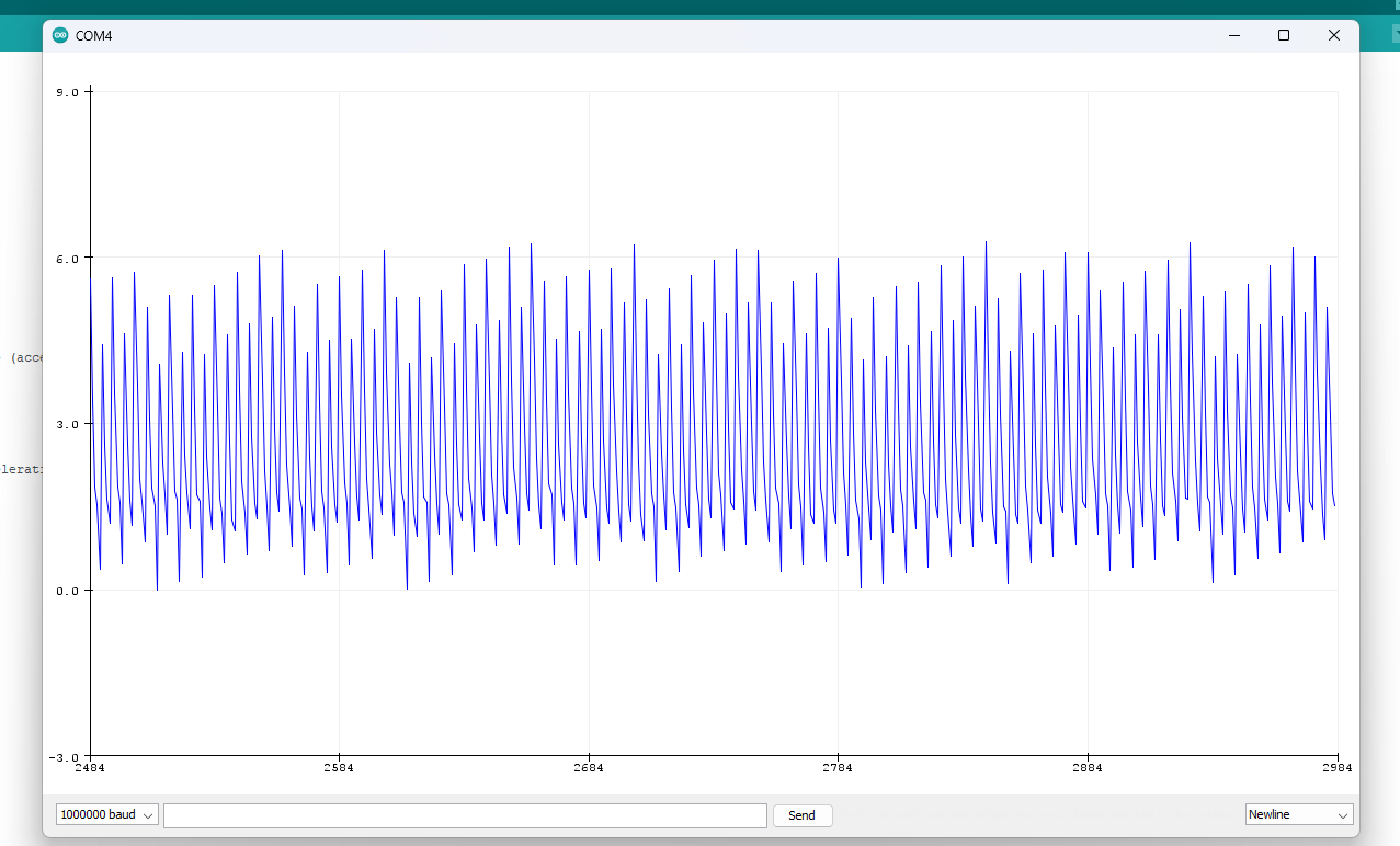
I think part of the problem may be inaccurate current data. I noticed the DC current is >45 mA even when the motor is not connected. The current waveform for each phase is centered around close to zero and seems to be about right but it’s pretty hard to check.
I doubt it is an adc calibration issue, though, I think it may be shoot through on the inverter stage. It’s low side sensing so the current going in on the low side of the inverter is what is measured, right. I may need inline and better, sensing… crap, pretty hard to know.
Maybe I should get on with the flagship board and then circle back to this when I know the hardware is better, also the effort to calibrate things won’t be useless.
^ that’s what appears to happen when I put the gain above 10,000 or so. The gain is compensated so it should not matter how often the observer function is run.
latest code:
#include <SimpleFOC.h>
#include <math.h>
// NUMBER OF POLE PAIRS, NOT POLES, specific to the motor being used!
BLDCMotor motor = BLDCMotor(7);
//this line must be changed for each board
BLDCDriver6PWM driver = BLDCDriver6PWM(A_PHASE_UH, A_PHASE_UL, A_PHASE_VH, A_PHASE_VL, A_PHASE_WH, A_PHASE_WL);
LowsideCurrentSense currentSense = LowsideCurrentSense(0.003, -64.0/7.0, A_OP1_OUT, A_OP2_OUT, A_OP3_OUT);
LowPassFilter diff_filter = LowPassFilter(0.05);
PhaseCurrent_s current1 = currentSense.getPhaseCurrents();
float goal_speed =0;
float v=2;
float v_diff=1;
float accel = 92;// in rads per second per second
float v_per_radsPS = 0.0232;
float accel_v_boost = 0.5;// voltage is increased during acceleration and deacceleration by this amount
bool voltage_override = 1;
float power_figure = 1.5;
float power_coeff = 0.00043;// the serial communicator could actually use an extra digit for this one.
float A, B, C;
float currentlf_now =0;
float prop_V= 0;
float min_V = 1;
float v_limit = 19;
float current_limit_slope = 1.8;// this is in milliamps pre rad per second
float current_limit_o_term = 200;//this is the current limit at zero rps, it may not trip with stall
float maybe_o = 1;
float Va = 0;
float Vb = 0;
float motortiming = 0;
void SerialComm(){
if (Serial.available() > 0){
switch(Serial.peek()){
case 't': Serial.read(); Serial.print("t"); Serial.println(goal_speed); break;
case 'c': Serial.read(); Serial.print("c"); Serial.println(accel); break;
case 'v': Serial.read(); Serial.print("v"); Serial.println(motor.voltage_limit, 4); break;
case 'n': Serial.read(); Serial.print("n"); Serial.println(v_diff); break;
case 'p': Serial.read(); Serial.print("p"); Serial.println(v_per_radsPS, 4); break;
case 'b': Serial.read(); Serial.print("b"); Serial.println(accel_v_boost); break;
case 'o': Serial.read(); Serial.print("o"); Serial.println(voltage_override); break;
case 's': Serial.read(); Serial.print("s"); Serial.println(motor.target); break;
case 'f': Serial.read(); Serial.print("f"); Serial.println(power_coeff, 6); break;
case 'g': Serial.read(); Serial.print("g"); Serial.println(currentSense.getDCCurrent(), 5); break;
case 'i': Serial.read(); Serial.print("i"); Serial.println(get_mA(), 4); break;
case 'j': Serial.read(); Serial.print("j"); Serial.println(min_V); break;
case 'w': Serial.read(); Serial.print("w"); Serial.println(driver.voltage_power_supply); break;
case 'k': Serial.read(); Serial.print("k"); Serial.println(v_limit); break;
case 'y': Serial.read(); Serial.print("y"); Serial.println(current_limit_slope); break;
case 'u': Serial.read(); Serial.print("u"); Serial.println(current_limit_o_term); break;
case 'e': Serial.read(); Serial.print("e"); if (motor.shaft_angle >= 0){
Serial.println(motor.shaft_angle, 3);
}
if (motor.shaft_angle < 0){
Serial.println((_2PI-(-1*motor.shaft_angle)), 3);
}
break;
case 'T': break;
case 'C': break;
case 'V': break;
case 'P': break;
case 'B': break;
case 'Y': break;
case 'U': break;
case 'O': break;
case 'F': break;
case 'J': break;
case 'W': ;break;
case 'K': ;break;
default: Serial.read(); break; //if anything we don't recognize got in the buffer, clear it out or it will mess things up.
}
}
if (Serial.available() >= 9){
switch(Serial.read())
{
case 'T': goal_speed = Serial.parseFloat();break;
case 'C': accel = Serial.parseFloat();break;
case 'V': v_diff = Serial.parseFloat(); break;
case 'P': v_per_radsPS = Serial.parseFloat(); break;
case 'K': v_limit = Serial.parseFloat(); break;
case 'B': accel_v_boost = Serial.parseFloat(); break;
case 'Y': current_limit_slope = Serial.parseFloat(); break;
case 'U': current_limit_o_term = Serial.parseFloat(); break;
case 'O':
maybe_o = Serial.parseFloat(); // just in case the wrong data gets in somehow we don't want the voltage going crazy
if (maybe_o < 1){
voltage_override = 0;
}
if (maybe_o >= 0.999){
voltage_override = 1;
}
break;// if it's not one of these, ignore it.
case 'F': power_coeff = Serial.parseFloat();break;
}
}
}
void overcurrent_trip(){// if it stalls this won't help except at higher powers, probably. Just helps prevent disaster
float current_cap = current_limit_o_term + fabs(motor.target)*current_limit_slope;
if (get_mA() > current_cap){
voltage_override = 0;
}
}
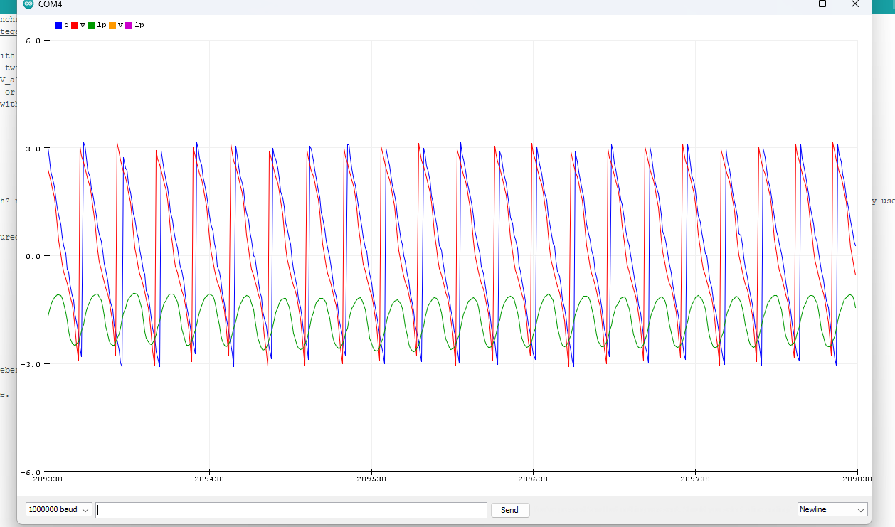
float track_return_motor_timing(float v_pA, float v_pB, float current_A, float current_B, float current_C, int outputorno) {
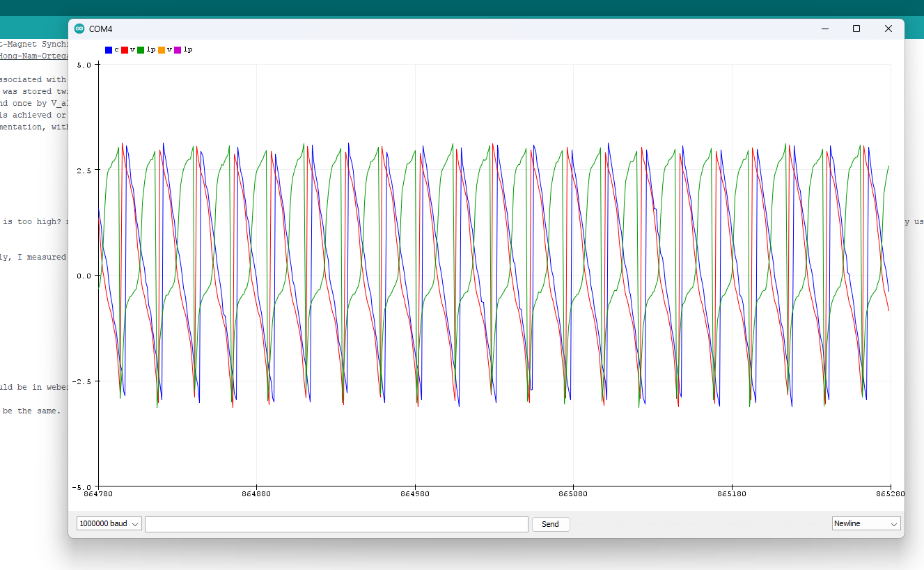
// Algorithm based on paper: Sensorless Control of Surface-Mount Permanent-Magnet Synchronous Motors Based on a Nonlinear Observer
// http://cas.ensmp.fr/~praly/Telechargement/Journaux/2010-IEEE_TPEL-Lee-Hong-Nam-Ortega-Praly-Astolfi.pdf
// In particular, equation 8 (and by extension eqn 4 and 6).
// The V_alpha_beta applied immedietly prior to the current measurement associated with this cycle
// is the one computed two cycles ago. To get the correct measurement, it was stored twice:
// once by final_v_alpha/final_v_beta in the current control reporting, and once by V_alpha_beta_memory.
// don't engage the system by calling this function until a suitable RPM is achieved or yu will just get nonsense results
//the basis of the code here is just dumbly adapted from the odrive implementation, with the removal of unnecessary features like the pll for speed tracking.
static float V_alpha_beta_memory_[] = {0.0f,0.0f};
static double flux_state_[] = {0.0f,0.0f};
static float last_v_alpha = 0.0f;
static float last_v_beta = 0.0f;
static float observer_gain = 1500.0f; //1500 seems to be about right, 3000 is too high? not clear actually. phase becomes nan somewhere between 10,000 and 15,000 could still be way too low. IDK what a reasonable starting point is, 1000 is what odrive uses. They use 2500 and 8000 in the pdf doc. Too high and it will bounce around, too low and it will take a long time to catch up with changes.
static float O_phase_resistance = 2.9f;// in ohms *presumably
static float O_phase_inductance = 0.0006455f; // in henries *presumably
static float O_flux_linkage = 0.00931f;// it's in units of webers *presumably, which is ampere-turns? Can be calculated from the peak to peak per hz, which is easy to measure, so find the equation for that and use that to calc it before then use that.*is this per phase or across terminals*??? I measured it across the terminals
static unsigned long last_run_ts = micros();
unsigned long mcs_since_last_run = ticks_diff(micros(),last_run_ts) ;
float s_since_last_run = float(mcs_since_last_run)/1000000.0f ;
float current_meas_period = s_since_last_run ;
static float one_by_sqrt3 = 0.5773502691f;
if ((current_meas_period * 1000 > 1.0f)) { // what should the coefficient be here? Just run it really fast for now. you can't because you have to be able to debug it. well ten times per oscillation should be fine, 60 rads per second test speed is 67 hz. so at least every 1/670 seconds
flux_state_[0] = 0.0f;
flux_state_[1] = 0.0f;
V_alpha_beta_memory_[0] = 0.0f;
V_alpha_beta_memory_[1] = 0.0f;
Serial.print("cmp too long:");
Serial.println(current_meas_period*1000000);
last_run_ts = micros();
return false;
}
if (get_mA()<70){ //assume measurement is invalid
current_A = 0.0f;
current_B = 0.0f;
flux_state_[0] = 0.0f;
flux_state_[1] = 0.0f;
V_alpha_beta_memory_[0] = 0.0f;
V_alpha_beta_memory_[1] = 0.0f;
//Serial.print("current too low:");
//Serial.println(get_mA());
last_run_ts = micros();
return false;
}
float I_alpha_beta[2] = {current_A, one_by_sqrt3 * (current_B -current_C)};
// alpha-beta vector operations
double eta[2] = {0.0f,0.0f};
for (int i = 0; i <= 1; ++i) {
// y is the total flux-driving voltage (see paper eqn 4)
float y = -O_phase_resistance * I_alpha_beta[i] + V_alpha_beta_memory_[i];
// flux dynamics (prediction)
float x_dot = float(y);
// integrate prediction to current timestep
flux_state_[i] += x_dot * float(current_meas_period);
// eta is the estimated permanent magnet flux (see paper eqn 6)
eta[i] = flux_state_[i] - O_phase_inductance * float(I_alpha_beta[i]);
}
// Non-linear observer (see paper eqn 8):
double pm_flux_sqr = O_flux_linkage * O_flux_linkage;
double est_pm_flux_sqr = (eta[0] * eta[0]) + (eta[1] * eta[1]);
double bandwidth_factor = 1 / pm_flux_sqr;
double eta_factor = 0.5f * (observer_gain * bandwidth_factor) * (pm_flux_sqr - est_pm_flux_sqr);
// alpha-beta vector operations
for (int i = 0; i <= 1; ++i) {
// add observer action to flux estimate dynamics
double x_dot = eta_factor * eta[i];
// convert action to discrete-time
flux_state_[i] += x_dot * current_meas_period;
// update new eta
eta[i] = flux_state_[i] - O_phase_inductance * I_alpha_beta[i];
}
// Flux state estimation done, store V_alpha_beta for next timestep
V_alpha_beta_memory_[0] = last_v_alpha; // still have to figure out exactly what voltage this is so we can sub in the right one
V_alpha_beta_memory_[1] = last_v_beta; // same here
last_v_alpha = v_pA;
last_v_beta = v_pB;
last_run_ts = micros();
float phase = atan2(eta[1], eta[0]); // do we have fast_atan available? no
float stator_field_angle = atan2(I_alpha_beta[0],I_alpha_beta[1]); // these might be the wrong way around fuck. This is the most likely.
float motor_timing = handle_wraparound_angle(phase, stator_field_angle, return_sign(motor.target));
if (outputorno == 1){
Serial.print("sfa:");
Serial.print(I_alpha_beta[0]);
Serial.print(", v_pA:");
Serial.print(v_pA);
Serial.print(", phase:");
Serial.println(phase);
return motor_timing;
}
if (outputorno == 0){
return motor_timing;
}
};
float handle_wraparound_angle(float angle_behind, float angle_ahead, int dir){
static float piepie = 6.2831853f;
if (dir == 1){ //clockwise drive
if (angle_behind < angle_ahead){ // they are in the same cycle
return (angle_ahead-angle_behind);
}
if (angle_behind > angle_ahead){ // the angle_ahead has gone past the end and wrapped around
return (piepie-(angle_behind-angle_ahead));
}
}
if (dir == 0){ //counter-clockwise drive
if (angle_behind > angle_ahead){ // they are in the same cycle
return (angle_ahead-angle_behind);
}
if (angle_behind < angle_ahead){ // the angle_ahead has gone past the end and wrapped around
return ((-1*piepie)-(angle_behind-angle_ahead));
}
}
}
unsigned long int ticks_diff(unsigned long int t2,unsigned long int t1){ //t2 should be after t1, this is for calculating clock times.
if (t2<t1){//t2 must have wrapped around after t1 was taken
return (4294967295-(t1-t2));
}
return (t2-t1);
}
float get_mA(){// this is the estimated current being drawn from the power supply, not the actual motor current which is a bit different
float x =0;
x = currentlf_now*motor.voltage_limit/24;
return 1000*((4.0384440932900223e-002)+3.4514090071108776e-002*x*30);// this is off by like 12 percent in some cases a polynomial of third order fits the data better but might flake out at higher than 500 mA so I didn't try it.
}
void setup() {
Serial.begin(1000000);
Serial.println("test serial2");
// driver config
// power supply voltage [V]
driver.voltage_power_supply = 24;
driver.init();
// link the motor and the driver
motor.linkDriver(&driver);
currentSense.linkDriver(&driver);
currentSense.init();
currentSense.skip_align = true;
FOCModulationType::SinePWM;
motor.voltage_limit = 1; // [V]
motor.velocity_limit = 300; // [rad/s]
motor.controller = MotionControlType::velocity_openloop;
motor.init();
motor.voltage_limit = 2;
goal_speed = 2;
}
float run_observer(){
current1 = currentSense.getPhaseCurrents();
A = current1.a;
B = current1.b;
C = current1.c;
Va = driver.dc_a * driver.voltage_power_supply-(driver.voltage_power_supply/2);
Vb = driver.dc_b * driver.voltage_power_supply-(driver.voltage_power_supply/2);
return track_return_motor_timing(Va, Vb, A, B, C, 0);
}
float run_observer_with_output(){
current1 = currentSense.getPhaseCurrents();
A = current1.a;
B = current1.b;
C = current1.c;
Va = driver.dc_a * driver.voltage_power_supply-(driver.voltage_power_supply/2);
Vb = driver.dc_b * driver.voltage_power_supply-(driver.voltage_power_supply/2);
return track_return_motor_timing(Va, Vb, A, B, C, 1);
}
int return_sign(float number){
if (number > 0){
return 1;
}
if (number <= 0){
return 0;
}
}
void loop() {
static unsigned long int loop_clock_in = micros();
unsigned long int loop_time = 0;
float loop_time_s = 0;
loop_time = ticks_diff(micros(), loop_clock_in);
loop_clock_in=micros();
loop_time_s = float(loop_time)/1000000;
if (motor.target < goal_speed-(accel*loop_time_s*1.5)){//rps not positive enough
if (motor.target < 0){//counterclockwise rotation, deaccelerating
motor.target = motor.target+accel*loop_time_s*0.7;
motor.move();
prop_V = (v_diff+accel_v_boost+fabs((motor.target*v_per_radsPS))+(power_coeff*pow(fabs(motor.target),power_figure)))*voltage_override;
}
run_observer();
if (motor.target >= 0){ //clockwise rotation, accelerating
motor.target = motor.target+accel*loop_time_s;
motor.move();
prop_V = (v_diff+accel_v_boost+fabs((motor.target*v_per_radsPS))+(power_coeff*pow(fabs(motor.target),power_figure)))*voltage_override;
}
}
run_observer();
if (motor.target>=goal_speed-(accel*loop_time_s*1.5)){//steady run phase
if (motor.target<=goal_speed+(accel*loop_time_s*1.5)){
motor.move();
prop_V = (v_diff+fabs((motor.target*v_per_radsPS))+(power_coeff*pow(fabs(motor.target),power_figure)))*voltage_override; //constant run
}
}
if (motor.target > goal_speed + (accel*loop_time_s*1.5)){ //rps too positive
if (motor.target > 0){ //clockwise rotation, deaccelerating
motor.target = motor.target-accel*loop_time_s*0.7;
motor.move();
prop_V = (v_diff+accel_v_boost+fabs((motor.target*v_per_radsPS))+(power_coeff*pow(fabs(motor.target),power_figure)))*voltage_override;
}
run_observer();
if (motor.target <= 0){
motor.target = motor.target-accel*loop_time_s; //counterclockwise rotation, accelerating
motor.move();
prop_V = (v_diff+accel_v_boost+fabs((motor.target*v_per_radsPS))+(power_coeff*pow(fabs(motor.target),power_figure)))*voltage_override;
}
run_observer();
}
if (prop_V < min_V){
motor.voltage_limit = min_V*voltage_override;
}
else {
motor.voltage_limit = prop_V;
}
if (prop_V > v_limit){
motor.voltage_limit = v_limit;
}
for (int i=0;i<10;i++){ // shouldloop at about 37 khz on b-g431 board
for (int q=0;q<5;q++){
motor.move();
motor.move();
motor.move();
run_observer();
motor.move();
motor.move();
motortiming = run_observer();
}
SerialComm();
}
//Serial.println(motortiming);
run_observer_with_output();
currentlf_now = currentSense.getDCCurrent();
currentlf_now = diff_filter(currentlf_now);// this updates the current for the get dc current, that function won't work unless this is called each loop
overcurrent_trip();
}
Another issue is that the observer may need to be run like clockwork, with the exact same time period in between runs every time. I don’t know how to arrange for this, it is a rather big function and I know you aren’t supposed to run such functions with interrupts, but maybe that is the only practical way for me. I can’t really write the whole program so that it runs the observer only once per main loop and then adjust the gain accordingly, there is too much else to do, and there will be more in the future, I don’t think the observer would run often enough.
I am thinking at least 10 times per electrical cycle is a reasonable frequency to run the observer? So at 10 rotations per second with a 7 pole pair motor 70*10 = 700 hz, or once every 1.4 msec. It is running more frequently than that now, I think, several times faster.