Need help driving bipolar stepper motors with low-resolution encoders

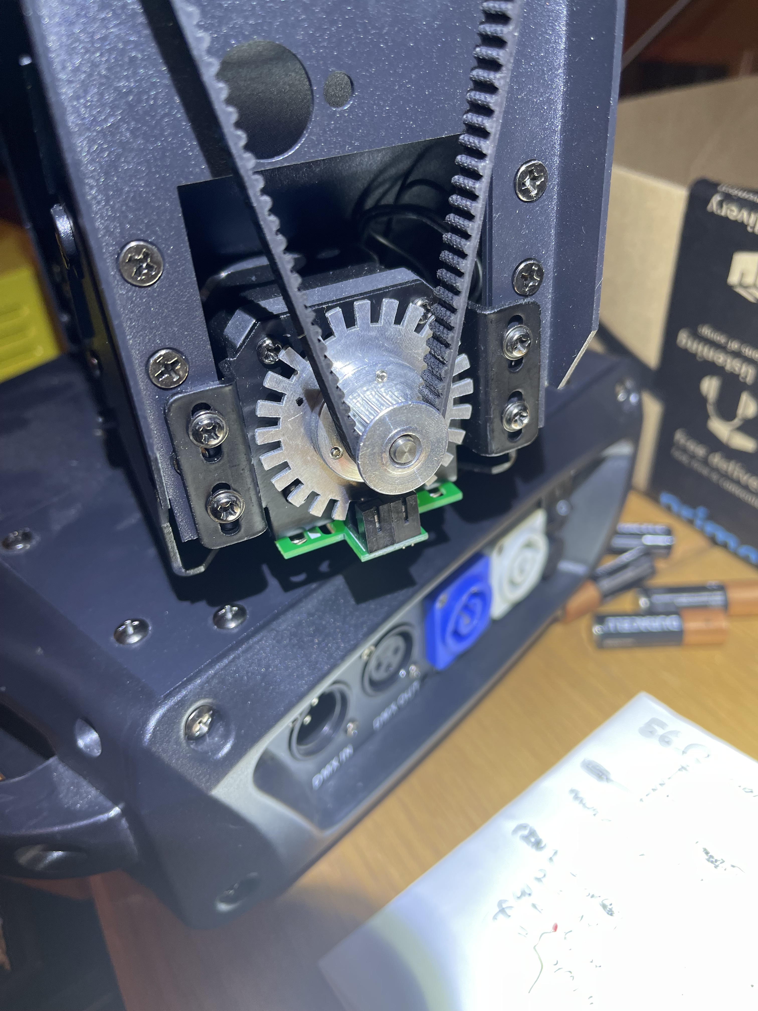
I’m currently trying to drive an unbranded unmarked bipolar stepper motor equipped with a pair of photointerrupters and a 24-flag wheel for an encoder. I’m using an l298n driver and a Pi Pico. The encoder works just fine in the encoder test sketch— I bug hunted the hell out of the missed pulses and now that’s fixed. Even so, I’m only able to run the motor in velocity-open loop mode, and only at a speed of between 1.5-2 rad/sec. Any lower or higher and it fails to start turning and grinds back and forth.

When I try to run it in angle-open loop mode, the motor locks in place but makes the classic “stepper motor hum” for about how long you’d expect it to move for. There is no motion or noise in any of the closed-loop modes— it just stays locked in place.

Unfortunately, I have seen discussions online about how simplefoc doesn’t play well with low cpr encoders. I don’t really have the option of adding a higher-resolution encoder to this project. I am trying to hack an existing chinesium moving stage light and interface with the existing electromechanical assembly. If the encoder is indeed the problem, is there anything I can do to cheat by like the OEM somehow did?

(On my phone, will add code shortly)

How many steps per revolution on the motor? With two photo sensors 90 degrees out of phase, I think you should get 96cpr on the encoder. Probably your best bet will be to use open loop until the velocity reaches some threshold and then switch over to closed loop with SmoothingSensor. Not sure if 1.5rad/s will be enough to get a good extrapolation. Plot smoothingsensor.angle_prev and see if it looks smooth or steppy. Try increasing motor.LPF_velocity.Tf and see if it helps. Try increasing the current limit during the open loop acceleration phase too. And ramp up the velocity so the rotor has time to get moving.

2 Likes

Thank you, that makes sense and I will report back after my shift tonight.

Oh, and I would guess that the smoothing sensor needs phase_correction = -motor.pole_pairs*_PI/96, i.e. half an encoder step, converted to electrical degrees. I’ve only used it with hall sensors where the encoder steps are synchronized with the commutation steps, so it could possibly be _PI/4 (half a commutation step), but I think half an encoder step is right. That should shift the angle so the average value is equal to what it would be without smoothing.