If you are just interested in understanding the performance of the encoder. Using a mechanical gearing between the stepper and the encoder would allow you to reduce the influence of cogging/poor PWM perfomance. A synchronous belt solution would be ideal.
you mean e.g. a bigger GT2 belt pulley on the sensor axis than on the stepper axis?
It’s not clear to me where the oscillations are coming from? Why would the error vary up and down in such a regular way? It doesn’t seem to correspond to the motor’s PP, right?
I have to think about how these could cause that kind of response in the error… its maybe possible, because these really are not great drivers.
That’s usually not a problem - it becomes a problem when the PSU voltage greatly exceeds the voltage limit and target voltages used, because then the PWM range gets very restricted. But usually the PWM range is a few thousand (depending on MCU type and clocks) so that when working with higher limits it’s not a problem.
I’d really like to unserstand the shape of the error - it would certainly explain the oscillations we get in velocity in some cases if the position is oscillating like this…
Careful - the HR timer can’t be used by SimpleFOC, and I really think it would be overkill.
You can set the driver.pwm_frequency - if you think the PWM resolution is the problem you could try lowering the pwm frequency to raise the resolution proportionally. At least I think it should - the stm32 PWM code is very complicated.
Regarding PWM resolution - how should SimpleFOC move the motor to a target angle with e.g. 16bit resolution when the PWM only has an e.g. 11bit resolution?
I played already with the PWM frequency between 5000Hz and 50000Hz to change the PWM resolution. No clear effect on the signal. PWM ABP clock is 72MHz on my STM32KC432.
What about dead time for L298? I have not set something here…
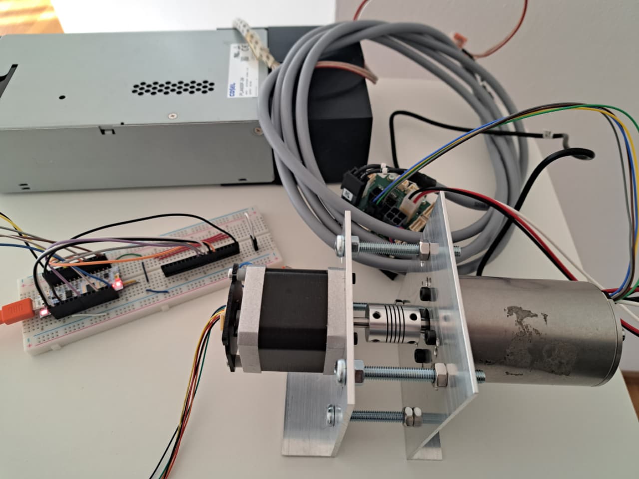
I work on mounting a Maxon BLDC motor/controller to the stepper to drive it with a constant speed.
HighRes PWM: yes, it looks scary in the big MCU manual. I thought about configuring it through STMCubeMX and copying the resulting code - I did that for CAN via STM32duino the same way. The of course a change to the SimpleFOC PWM routines would be needed.
But let’s first see the signal when the stepper is passively turned by the Maxon.
While you are quite correct that the PWM resolution is related to the position accuracy, it’s not that directly related that you can say target position resolution bits depend on the PWM resolution bits.
The position of the motor in terms of a target angle is in the coordinates of the physical rotations, e.g. the position can vary between 0-2PI and that’s a full turn of the motor.
But the commutation waveform generated by the PWM controls the electrical revolutions, in the electrical coordinate system - and here there are N electrical revolutions per physical one, where N==pole pairs. So the resolution is effectively N x higher because of this.
Furthermore, the waveform (let’s say we use sine wave shaped commutation) goes up, down past zero, and the up again, so there are four quadrants within which the same PWM levels are used “upwards” and “downwards” to make a sine wave. So this again multiplies the effective resolution by x2…
And further, the commutation waveform is discretized only in one axis by the PWM resolution, while the discretization in the time/angle axis is actually given by the sample rate or loop iteration frequency.
So you can think of the PWM levels discretizing the Y axis, and the iteration speed (how often you make the call to loopFOC() to change the PWM level) is discretizing the Y axis, and into this discretized XY space the algorithm is plotting a sine wave (the commutation waveform)…
In terms of a stepper with 50PP I would not expect a problem with the PWM levels, since the effective PWM resolution is x100 compared to the physical rotations.
But I would expect the problems with respect to the X axis (time/angle) as the high pole count means you have to generate 50 electrical revolutions per physical, and an error in the physical angle translates into a 50x larger error in terms of the electrical angle.
So even small amounts of error or sensor latency can have a large effect…
So can a can still hope - sniff…
Thanks for clarifying! I wish that all these theoretical basics are documented in the wiki. I see a lot of people messing with hardware designs - as I also did - and then learn about the real requirements at the end.
To summarize your input: for motors with low polepair numbers like BLDC you need high PWM resolution and not so much sensor resolution. For high polepair numbers like steppers you need high sensor resolution and not so much PWM resolution.
And now we come to my idea of spinning the stepper/sensor with an external motor.
I set the motor to 120RPM, as at lower speed the movement is not very smooth. Even at this speed you don’t see a straight line, but some deviations in speed on it.

Then I changed the sampling period and just moved the axis by hand:

So coming back to my former investigation -
- how do the new curves fit into this? Being driven externally, the sensor output seems reasonable. But why then do I see this strange signal when the stepper itself turns in 6400 (windowsize * polepairs) steps during the calibration routine?
Further ideas how to track this down?
It’s hard to see, but does it look like this line has the same small oscillations as the other picture, where we see ±0.2rad oscillations in the close-up?
It’s a really good question. At the moment I don’t really have an idea where it is coming from.
One question I wonder about is the frequency of the oscillations - is it dependent on speed or only on position? Do the oscillations look the same if you change the frequency of the calls to move() relative to the speed of rotation, e.g. could it be an artefact of sampling or of some kind of filtering?
I changed the code to read the angle instead the raw position and converted the reading in gnuplot to degrees to make the two diagrams comparable.
As this diagram is recorded at 120RPM and the calibration giving me the other diagram runs at ca. 5RPM, the x-axis here is streched by factor 24.I think you can see that there is no ±0.2deg oscillation. The deviation from a straight line come from variations in speed at the driving Maxon motor - it only has a Hall sensor, no Mt6835 ;-). The stepper does nothing, I disabled motor.move, i just use the sensorcode:
for (int i=0;i<1000;i++)
{
sensor.update();
// sensorbuffer[i] = sensor.readRawAngle21();
sensorbuffer[i] = sensor.getAngle();
// delay(10);
}
for (int i=0;i<1000;i++)
{
// printf(“\r\n%u %u”,i,sensorbuffer[i]);
printf(“\r\n%u %.4f”,i,sensorbuffer[i]);
}

Hola!
Does the reading jump around if you measure without powering the coils. Also, how about in open-loop angle mode, just holding a random angle.
I know this is finicky, but running the CORDIC vs. SFOC (_sin & _cos) test, I did see some oscillations in the output curves. Maybe your assumption, that it’s related to motor-control, could hold true? So maybe the sensor is simply so good, that it picks up, what other sensors does not or filter out.
On a BLDC with few pole pairs, those angle oscillations don’t have a detrimental effect, I think. But for precision machining, it may show up as artifacts in the work.
The L298 is renowned for being slow, like you pointed out yourself.
If the oscillations happens while it’s holding an angle in open-loop angle mode, and there are no oscillations while the motor is idle, then for sure it has something to do with the L298.
Edit: I ordered magnets yesterday, so it gonna take some time before I can join the test. I ended up with the 150C rated 8x2.5mm (Radial Magnets) from DigiKey.
short intermediate report: I now have a second MT6835 mounted on the Maxon motor in ABZ mode and 14bit resolution. I lost some time figuring out that programming the sensor via SPI does NOT work on a STM32 because the driver contains one bug and also uses a non-portable union data structure which results in 24bit commands being sent in the wrong order to the sensor. I will file a bug report on that. For 8bit MCU users the code is fine!
I did a quick test on the Maxon EPOS4 controller to verify that I now have a more constant velocity when driving the stepper/primary MT6835 test target with the Maxon. The velocity is maintained with around ±1RPM at e.g. 64RPM. I hope this is precise enough to get good results for the test target. I will come back with new diagrams.
2 Likes
Im seeing some weird behavior from the MT6835. Could this be related to the bug you describe @husky ? (Using STM32G4)
When the MCU is in DFU mode, no SPI activity. The LED (On MT6835 PWM output) is outputting what I would expect, low to full brightness in a full rotation.
If I then read these registers:
Read Register 0x003: 11111111
Read Register 0x004: 11111111
Read Register 0x005: 11111111
Read Register 0x006: 0
Read Register 0x007: 0
Read Register 0x008: 11111111
using this from the MT6835 driver
uint8_t MT6835::readRegister(uint16_t reg) {
    MT6835Command cmd;
    cmd.cmd = MT6835_OP_READ;
    cmd.addr = reg;
    transfer24(&cmd);
    return cmd.data;
};
This it the output from readRawAngle21(); no matter how the magnet is oriented.
Get RAW: 101010101010101010101
Reading Zero position with getZeroPosition();
HEX:  FFA
DEC:  4090
BIN:  111111111010
Is this correct? Should it read registers 0x003 to 0x006 (MT6835_REG_ANGLE1 to MT6835_REG_ANGLE4) →
uint32_t MT6835::readRawAngle21(){
    uint8_t data[6]; // transact 48 bits
    data[0] = (MT6835_OP_ANGLE<<4);
    data[1] = MT6835_REG_ANGLE1;
    data[2] = 0;
    data[3] = 0;
    data[4] = 0;
    data[5] = 0;
    if (nCS >= 0)
        digitalWrite(nCS, LOW);
    spi->beginTransaction(settings);
    spi->transfer(data, 6);
    spi->endTransaction();
    if (nCS >= 0)
        digitalWrite(nCS, HIGH);
    return (data[2] << 13) | (data[3] << 5) | (data[4] >> 3);
};
Or is it intended for burst mode ?
Right, I see it is for burst mode → #define MT6835_OP_ANGLE 0b1010
There ya go! Finally
This works on STM32G4
uint8_t data0 = 0x00;
uint8_t data1 = 0x00;
uint8_t angle_buffer[3];
uint8_t data5 = 0x00;

uint32_t getRaw21bitMT6835(){


  digitalWrite(PD2, LOW); // manually take CSN low for SPI_1 transmission
  data0 = SPI.transfer(0xA0, SPI_CONTINUE); //Send the HEX data 0xA0 over SPI-1 port and store the received byte
  data1 = SPI.transfer(0x003, SPI_CONTINUE); //Send the HEX data 0x003 over SPI-1 port and store the received byte
  angle_buffer[0] = SPI.transfer(0x00, SPI_CONTINUE); //Send the HEX data 0x00 over SPI-1 port and store the received byte
  angle_buffer[1] = SPI.transfer(0x00, SPI_CONTINUE); //Send the HEX data 0x00 over SPI-1 port and store the received byte
  angle_buffer[2] = SPI.transfer(0x00, SPI_CONTINUE); //Send the HEX data 0x00 over SPI-1 port and store the received byte
  data5 = SPI.transfer(0x00, SPI_LAST); //Send the HEX data 0x00 over SPI-1 port and store the received byte
  digitalWrite(PD2, HIGH); // manually take CSN high between spi transmissions

  /*
  SerialUSB.println("Read Register 0x003:  ");
  SerialUSB.println(data0, BIN);
  SerialUSB.println(data1, BIN);
  SerialUSB.println(angle_buffer[0], BIN);
  SerialUSB.println(angle_buffer[1], BIN);
  SerialUSB.println(angle_buffer[2], BIN);
  SerialUSB.println(data5, BIN);
  */

  uint32_t buff_shift = (angle_buffer[0] << 13) | (angle_buffer[1] << 5) | (angle_buffer[2] >> 3);
  return buff_shift;

  }
Output:
34,101110010011010101101,4.5457034
35,101110010011011000010,4.5457664
36,101110010011011100100,4.5458684
37,101110010011100011100,4.5460362
38,101110010011101100111,4.5462608
39,101110010011111011101,4.5466142
40,101110010100001000000,4.5469108
41,101110010100011001111,4.5473394
42,101110010100101101110,4.5478158
43,101110010100111110001,4.5482082
44,101110010101001100000,4.5485406
45,101110010101010100010,4.5487385
46,101110010101100100110,4.5491338
47,101110010110000000110,4.5498052
48,101110010110100001000,4.5505781
49,101110010111001110011,4.5516658
50,101110011001101000000,4.5553479
51,101110101000011001010,4.5780039
52,101111010011110010000,4.6445584
53,101111110101010001111,4.6959438
54,110000001111110010101,4.7366123
55,110000100101011001011,4.7697544
56,110000111010111101000,4.8028221
57,110000111100010010010,4.8048654
58,110000111100011100100,4.8051109
59,110000111100010100011,4.8049164
60,110000111100010000000,4.8048115
61,110000111100001111101,4.8048024
62,110000111100001111101,4.8048024
63,110000111100011000110,4.8050213
64,110000111100101100111,4.8055034
65,110000111101000101110,4.8060999
66,110000111110010110110,4.8080411
67,110001000110000011100,4.8198519
68,110001100101110010111,4.8685408
69,110001111100101110111,4.9037261
70,110010001101000110101,4.9288392
71,110010001101110110010,4.9299808
72,110010001110100000001,4.9309845
73,110010010010011001001,4.9369526
74,110010100110001011011,4.9673028
75,110010111110111001110,5.0052295
76,110011001011100100100,5.0246620
77,110011010010011010101,5.0351634
78,110011011110100000101,5.0537148
79,110011011110110100000,5.0541792
80,110011100000000110001,5.0561476
81,110011100110011111010,5.0659537
82,110100000100001111110,5.1116018
83,110100011101100011010,5.1504188
84,110100101101111100000,5.1755552
85,110100110000001111110,5.1790967
86,110100110011011101110,5.1840343
87,110101001000100100010,5.2164035
88,110101101010101111110,5.2688346
89,110101111100111010101,5.2967072
90,110101111110110001000,5.2995443
91,110101111111010010001,5.3003383
92,110110000001011101000,5.3036666
93,110110001000110010101,5.3149228
94,110110101001000011101,5.3644180
95,110111000000010100000,5.4000921
96,110111001110110001010,5.4222689
97,110111001111111110000,5.4241085
98,110111010000101111100,5.4252949
99,110111010101001001000,5.4320416
100,110111101011101110110,5.4666944
I don’t see any jumping around ?
0,101000101100001100111,3.9947946
1,101000101100001100111,3.9947946
2,101000101100001100111,3.9947946
3,101000101100001100111,3.9947946
4,101000101100001100111,3.9947946
5,101000101100001100111,3.9947946
6,101000101100001100111,3.9947946
7,101000101100001100111,3.9947946
8,101000101100001100111,3.9947946
9,101000101100001100111,3.9947946
10,101000101100001100111,3.9947946
11,101000101100001100111,3.9947946
12,101000101100001100111,3.9947946
13,101000101100001100111,3.9947946
14,101000101100001100111,3.9947946
15,101000101100001100111,3.9947946
16,101000101100001100111,3.9947946
17,101000101100001100111,3.9947946
18,101000101100001100111,3.9947946
19,101000101100001100111,3.9947946
20,101000101100001100111,3.9947946
21,101000101100001100111,3.9947946
22,101000101100001100111,3.9947946
23,101000101100001100111,3.9947946
24,101000101100001100111,3.9947946
25,101000101100001100111,3.9947946
26,101000101100001100111,3.9947946
27,101000101100001100111,3.9947946
28,101000101100001100111,3.9947946
29,101000101100001100111,3.9947946
30,101000101100001100111,3.9947946
31,101000101100001100111,3.9947946
32,101000101100001100111,3.9947946
33,101000101100001100111,3.9947946
34,101000101100001100111,3.9947946
35,101000101100001100111,3.9947946
36,101000101100001100111,3.9947946
37,101000101100001100111,3.9947946
38,101000101100001100111,3.9947946
39,101000101100001100111,3.9947946
40,101000101100001100111,3.9947946
41,101000101100001100111,3.9947946
above was with a delay(10); I will try to fill a buffer.
0,101000101100001101101,3.9948127
1,101000101100001101101,3.9948127
2,101000101100001101101,3.9948127
3,101000101100001101101,3.9948127
4,101000101100001101101,3.9948127
5,101000101100001101101,3.9948127
6,101000101100001101101,3.9948127
7,101000101100001101101,3.9948127
8,101000101100001101101,3.9948127
9,101000101100001101101,3.9948127
10,101000101100001101101,3.9948127
11,101000101100001101101,3.9948127
12,101000101100001101101,3.9948127
13,101000101100001101101,3.9948127
14,101000101100001101101,3.9948127
15,101000101100001101101,3.9948127
16,101000101100001101101,3.9948127
17,101000101100001101101,3.9948127
18,101000101100001101101,3.9948127
19,101000101100001101101,3.9948127
20,101000101100001101101,3.9948127
21,101000101100001101101,3.9948127
22,101000101100001101101,3.9948127
23,101000101100001101101,3.9948127
24,101000101100001101101,3.9948127
25,101000101100001101101,3.9948127
26,101000101100001101101,3.9948127
27,101000101100001101101,3.9948127
28,101000101100001101101,3.9948127
29,101000101100001101101,3.9948127
30,101000101100001101101,3.9948127
31,101000101100001101101,3.9948127
32,101000101100001101101,3.9948127
33,101000101100001101101,3.9948127
34,101000101100001101101,3.9948127
35,101000101100001101101,3.9948127
36,101000101100001101101,3.9948127
37,101000101100001101101,3.9948127
38,101000101100001101101,3.9948127
39,101000101100001101101,3.9948127
Timing the SPI read with SPI.setClockDivider(SPI_CLOCK_DIV16); (168/16 = 10,5 Mhz)
Timing in micros();
Iterations:   700
elapsed_ticks:   9339.0000
time per iteration:   13.3414
Using the SPI.beginTransaction(settings); did not make a difference. Having it around the SPI.transfer actually increased the time to 21 micros.
Pushing it with SPI.setClockDivider(SPI_CLOCK_DIV8); Don’t know if the data is corrupted.
Iterations:   700
elapsed_ticks:   7738.0000
time per iterasion:   11.0543
The data does look ok w. 21Mhz
70,100110011100111010100,3.7749951
71,100110011100111010100,3.7749951
72,100110011100111010100,3.7749951
73,100110011100111010100,3.7749951
74,100110011100111010100,3.7749951
75,100110011100111010100,3.7749951
76,100110011100111010010,3.7749889
77,100110011100111010010,3.7749889
78,100110011100111010010,3.7749889
79,100110011100111010010,3.7749889
80,100110011100111010010,3.7749889
I was able to change the 0x00E register by doing the EEPROM routine.
uint8_t MT6835_STM32G4::readMT6835_CAL_FREQ(){
    uint8_t CAL_FREQ = 0;
    digitalWrite(nCS, LOW); // manually take CSN low for SPI_1 transmission
    SPI.transfer(0x30, SPI_CONTINUE);
    SPI.transfer(0x00E, SPI_CONTINUE);
    CAL_FREQ = SPI.transfer(0x00, SPI_LAST);
    digitalWrite(nCS, HIGH); // manually take CSN high between spi transmissions
    return CAL_FREQ;

};

uint8_t MT6835_STM32G4::writeMT6835_CAL_FREQ(){
    uint8_t WRITE_CAL_FREQ = 0;
    digitalWrite(nCS, LOW); // manually take CSN low for SPI_1 transmission
    SPI.transfer(0x60, SPI_CONTINUE);
    SPI.transfer(0x00E, SPI_CONTINUE);
    WRITE_CAL_FREQ = SPI.transfer(0x7F, SPI_LAST);
    digitalWrite(nCS, HIGH); // manually take CSN high between spi transmissions
    return WRITE_CAL_FREQ;

};


/**
 * Wait 6s after calling this method
 */
bool MT6835_STM32G4::writeEEPROM(){

    digitalWrite(nCS, LOW); // manually take CSN low for SPI_1 transmission
    SPI.transfer(0xC0, SPI_CONTINUE);
    SPI.transfer(0x00, SPI_CONTINUE);
    if (SPI.transfer(0x00, SPI_LAST) == MT6835_WRITE_ACK){
    digitalWrite(nCS, HIGH); // manually take CSN high between spi transmissions
    return true; }
    else {digitalWrite(nCS, HIGH); // manually take CSN high between spi transmissions
    return false;}

};
I did a calibration routine, running 4 rad/s and it succeeded. Now the weird behavier in closed loop is gone. This is with the two small axial magnets put on the side. I considered waiting for the proper magnets. But hay, it works !
1 Like
Update: the dev branch of the drivers library now contains bug-fixes for the MT6835 driver to fix the problems @husky found.
Basically, the register read/write functions were all wrong due to byte order and bitfield order problems.
I’ve fixed this, and the driver seems to be working now, at least on STM32 MCUs.
The angle reading was working before already, since it was handling the transfer in a different way.
@Juan-Antonio_Soren_E you could try the driver again now, it should work on your STSPIN32…
1 Like
![]()
uint16_t MT6835_STM32G4::getRaw16bitTIM3(){

return TIM3->CNT;

}
I am back with some charts!
And I changed the measuring method a little bit: as I can’t measure positions with >14bits accuracy (no sponsor for a 21bit optical encoder), instead I recorded 500 samples with 2ms clock and let the stepper or Maxon spin at 60RPM. Then I calculated the line of least deviation and plotted for each measured angle its deviation from that line.
Testbed: my stepper is coupled to a Maxon (8 pole pairs) with its own controller. One MT6835 is attached with ABZ wires to that Maxon controller to get smooth velocity. The SPI wires go to my SimpleFOC controller so that I can either record the Maxon sensor SPI 21bit angle or the second MT6835 SPI 21bit angle.
First chart: Stepper is running openloop at 60RPM, sensor on Maxon is recorded, 10mm magnet, sensor system bandwidth is set to factory setting=5=medium noise. I had to extend @runger
code with setOptions5 routines to access the respective register. Chip is user calibrated.

Second chart: Only bandwidth was changed to 0=minimum noise. A slight improvement is visible.

Third chart: Sensor on stepper is now recorded. 6mm magnet. Bandwidth setting=0. Chip is user calibrated.
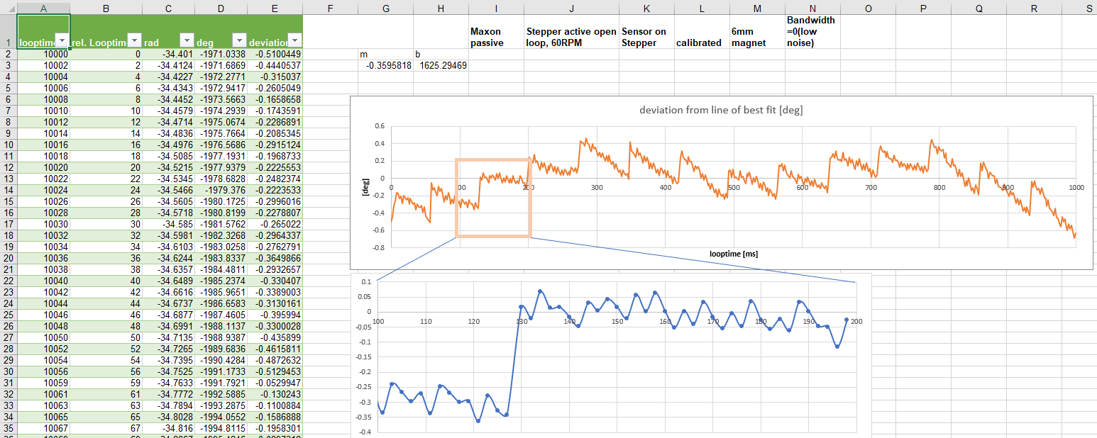
- on all charts we see deviations from the ideal y=0 line up to ±0.6 degrees on one physical rotation.
- the signals of the two sensors differ slightly in their spectrum, maybe to mech. resonances?
- the third chart is the most relevant as it shows the intended target system. We see 14 signal groups on a single mech. turn. How is this “14” related to anything in the setup?
- If this sawtooth thing wouldn’t exist, we talk about deviations in the range of 0.05 to 0.1 degrees.
- Hypothesis: any kind of filtering this signal will introduce phase shifts which conflict with the need to get precise absolute position readouts
- A stepper with no SimpleFOC, but with e.g. 1/4 microstepping, reaches around 0.2 degrees resolution, with the risk of loosing full 0.9deg steps, of course. This is around 11bit resolution
- Currently I see no way to get significantly beyond that 11bits by using magnetic encoders. Too many open questions. Only optical >18bit encoders (due to 6bit loss by transforming 1 mech turn into 50 electrical turns) would help, costing several hundred Euros.
I’m mostly trying to stay out of the way while the adults are talking, but I did undertake a calibration thing with micropython and an as5600, and learned a lot about magnetic angle sensors and stuff along the way. Clearly part of our problem is that the foundation is a bit shaky i.e. even the drivers have errors in them and stuff… but I agree that I don’t think getting something like more than 11 bits of de facto precision i.e. repeatability, is practical with these devices. Also I think the actual accuracy must be far less. If you have a 200 step per rotation stepper motor and wish to regulate the angle between the rotor and magnetic field to within say 10 percent of the optimal 90 degrees, that’s 9/200 = 0.045 degrees, in terms of absolute rotation. The combined sum of all errors will surely be far higher than that? That seems pretty precise. I like the magnetic sensors for several reasons, but I think they are best used with stepper motors when combined with the drivers like a tmc2209 driver, which can detect lost steps and control current and voltage vs time waveforms better than I think is practical with SimpleFOC running on even the finest STM32.
Juan seems to be building some kind of CNC machine, and the angle sensors can be used to give a certain resiliency that is useful in routers, for instance. The tmc2209 can tell you you missed a step, but it may be more than one and something might get missed. The angle sensor can tell you what happened so you can correct for it.
Although I certainly admire the skill and effort put into it, I have to admit that actually using them to control the magnetic or electric field seems like a difficult and not very practical proposition, even with good calibration.
I also think that the so called calibration approaches are missing some important factors; as noted in my post on magnetic sensor calibration under micropython, non linearities between electrical angle and rotor angle arise even during low speed. Unless an actual optical sensor is used to correlate mechanical angle to sensor reading, the sources of error may be getting baked in and be part of the (to me at least!) baffling phenomena described above. Consider that the very small angular errors could be leading to overshooting the desired 90 degree angle, which quickly leads to a loss of a step. A lot of stuff could start to go wrong at that point.
Not to try to discourage any efforts on any front, and here’s hoping this sensor will pan out :).