Motor runaway in Current Mode - Potential Phase Lag or Offset Error

Subject: Custom FOC implementation - Motor runaway and Iq/Id coupling at high speed

Hello everyone,

I am developing my own FOC implementation (not using the SimpleFOC library itself) and I’m facing a persistent “runaway” issue that I haven’t been able to solve. I would appreciate some expert insight into what might be happening.

The Problem: The motor operates fine at lower speeds, but as it accelerates, it enters a runaway state. Specifically, in Current Control mode:

  • If I command Iq = 5A, the motor spins as expected.

  • If I then command Iq = -5A to reverse, the motor instead accelerates rapidly in the opposite direction.

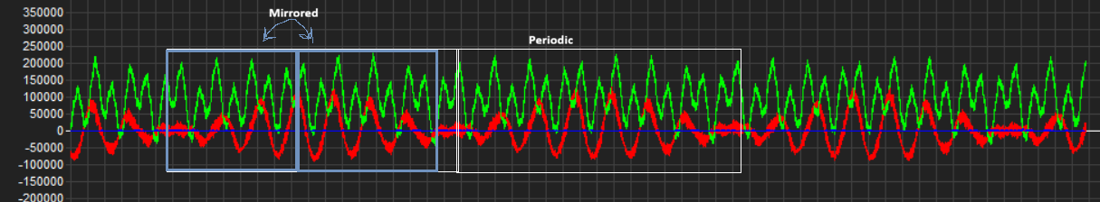
  • During this runaway, I observe that both Iq and Id go to approximately -5A.

What I’ve tried:

  1. Manual Offset: I haven’t implemented an automated encoder calibration routine yet. I am using a manual offset and I’ve tried to align the zero_electric_angle as accurately as possible.

  2. Angle Delay Compensation: I suspected phase lag, so I attempted to implement an angle delay compensation (predicting the angle based on velocity), but the runaway persists above certain RPMs.

Additionally, I would like to know if implementing a feed-forward Back-EMF compensation is strictly necessary to prevent this runaway. I have already attempted to implement it in my code, but it resulted in a very limited top speed, far below what the motor should be capable of. Given that my current manual offset might be slightly off, could the lack of proper Back-EMF compensation (or a poorly tuned one) be contributing to the loss of synchronization and the subsequent runaway, or should the standard PI current loops be able to handle this as long as the angle is correct?

Is there any zero_electric_angle setting that reverses the behavior, so it runs away in positive direction but works with negative current?

How are you judging the accuracy of your zero_electric_angle? I use voltage control mode and adjust until the speed for a given voltage is equal in both directions.

Your current control loop should always push Id toward zero, so investigate why it isn’t. Print out all the relevant variables so you can manually run all the calculations your current PID does and see if you can find what’s preventing it from working.

Hi,

The

you mentioned sounds like something I was struck with earlier. Is there any chance you are using Low-Side current sensing?

I am using inline current sensing and sampling the ADC via DMA triggered at the PWM center-aligned interrupt. This part seems to be working correctly, as the current measurements are clean.

However, I recently encountered an issue while verifying a new calibration and the zero angle compensation. In the attached image, the green curve represents the encoder (electrical angle) error based on the open-loop position, and the red curve shows the error after applying the calibration. Ideally, the calibrated error should be close to zero, but instead it exhibits a sinusoidal behavior.

Additionally, the original encoder error appears to have a mirrored pattern, which suggests something unusual. Because of this periodic variation, the calibration lookup table does not seem to be compensating the error properly.

For reference, I am using the MT6835 without performing any internal calibration via its IC configuration pins.

I am using a frameless BLDC motor with an integrated gearbox, so I am not sure if this behavior could also be related to friction effects.

I see.

Using inline current sensing, you don’t really have to time the sampling moment with PWM. At first I suspected the phenomenon where your phase PWM reaches 100% duty cycle leaving no interval for the low-side current sensing, but it was not the case for you.

One more thing to check is that whether your code has anti-windup for the PID controller. When I wrote my own FOC code I actually forgot about that (which SimpleFOC has), so my integral term kept increasing forever, to the point where my motor would spin extremely fast, then slow down, then spin in the reverse direction fast. D-Q current kept increasing forever, despite being stable at first. Check if your code has a limit for how large the integral term can reach to see if it fixes your problem.

Regarding your recent issue with zero e-Angle, I did indeed encounter that. Here is a picture of my e-Angle error, where the blue line represents CW error, the orange line represents CCW error, and the green flat line is the ideal difference (pi/2), all within 1 physical revolution, all in radians:


Doesn’t mine look similar to yours? I see this on almost every motor I worked with. If you pay really close attention, it is sinusoidal in 2 ways, like as if it is merged from 2 sinusoidal signals. The first sinusoidal wave is the big one, and if you count the periods of the orange line you would find 7, which matches my motor’s pole pairs count. So I’m guessing cogging torque is causing this. The second sinusoidal wave is the small wiggles, which I think is due to noises of the encoder (I used AS5048A).

Friction, magnet eccentricity, and encoder’s linearity can heavily affect your angle reading (Linearity error is also discussed in the MT6835 datasheet). For high performance and ultra-precise control, people usually have LUT for compensating for these. But for hobbyist I think they are quite neglectable. If you want really clean angle readings, try cogging torque compensation and eccentricity compensation first, you’d be surprised by how effective they are.

Edit: I just remembered, since you mentioned that

I think you should have a look at your control loop update frequency. If the control loop is not updating fast enough, it cannot handle new e-Angle position for Park and Clarke. This is very evident on higher RPMs. Typically I would aim for above 16kHz of FOC update loop, but 5-10kHz is sufficient for most hobbyist projects (Odrive uses 8kHz though).

My control loop runs at 23 kHz (same as PWM). Inline current sensing still has switching noise, so center-aligned sampling is preferable.

The red curve shows ~34° peak-to-peak electrical angle error. This is likely affecting velocity and angle estimation above 500 RPM.

Does this make sense, or should 34° p-p still be acceptable for a 14 pole-pair BLDC?

I’ll recalibrate while reducing encoder tilt to see if the sinusoidal error changes. Then I’ll check if gearbox friction is significantly affecting the system.

MT6835 is an awesome encoder. It doesn’t give you a perfect reading directly, but the precision is so high that you can calibrate it very well. Steppers are much better than BLDC, due to their very uniform step size. If you make the lookup table one entry per step, you get very good linearity. It’s probably not possible on a motor with integrated gearbox, but it would be best to have a stepper rotate the BLDC motor and read the sensor to see what value it gives at each step. Then copy that lookup table over to the BLDC’s driver.

For 3-phase BLDC, try setting the LUT size to the number of cogging steps (84 for 12N14P). At each step, one magnet pair will be centered on one stator tooth pair, so should position more consistently than inbetween angles. And try running the motor in open loop velocity mode and adjust motor.voltage_limit until it gives the smoothest motion. Then use that for motor.voltage_sensor_align during calibration.

Interesting thought: Unlike lowside sensing, you could sample at twice the PWM frequency to get more sensor noise averaging. Both the highside and lowside center times will be free of switching noise.

Okay,

~34 deg p2p error, so I’d assume ~17 deg on each side, which is quite significant for eAngle, but considering your motor has 28 poles, I think we can live with that.

However I still do not think the error is causing problem for the velocity controller. I worked with some motors with old rusty strain-wave gear with really high friction and they gave really poor eAngle error, like up to 60 deg p2p. But my velocity controller doesn’t really seem to care much, and the only difference was that the temperature would rise higher and faster than if I removed the gearbox and calibrated the motor properly.

So about the eAngle error, like many people on the forum said, it will cause your motor temp to rise, and the motor will spin faster on one direction than the other. Current consumption asymmetry could also be seen. But unless the error is really large, like very close to 90 deg, I do not think it will cause big troubles for the velocity loop.

Edit: Again, check if you did have anti-windup for your PID, because that was my first motor-going-crazy cause.