This motor moves but does not even turn using FOC. Perhaps the PP check fail has something to do with it?
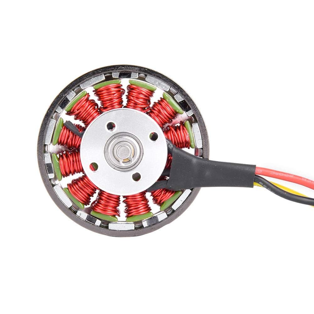
Please see debug output below. The motor I am using has 14 magnets on the rotor and 12 coils on the stator. It is easy to see and count the magnets.
I checked the encoder using the encoder example. When I rotate the motor by hand through one revolution, the angle changes by about 6.3 radians. It is an A/B quarature encoder with 600 PPR.
I use this code to instatiate the BLDCMotor class BLDCMotor motor = BLDCMotor(7, 0.24);
How is it that the PP check fails? I thought 14 physical magnet implies 7 pairs. The estimate comes out different each time and might be 13.7 or 14.2 or something around there.
Update. Neither suggestions in my message below really fits as your sensor is giving 6.2 radians. Interrupt noise?
Can you show your sensor config code. Try doubling ppr to 1200.
The rationale is that you’re 600ppr encoder might have double the interrupts (rising/falling)
Or you could try changing pp to 14 (but you say there are only 14 magnets so 7pp seems right)
The encoder example continously reads out the encoder and prints the serial terminal. I rotate the encoder once and see the angle change by about 6.3 radians. I think this is good enough to prove that the encoder is not off by a factor of 2.
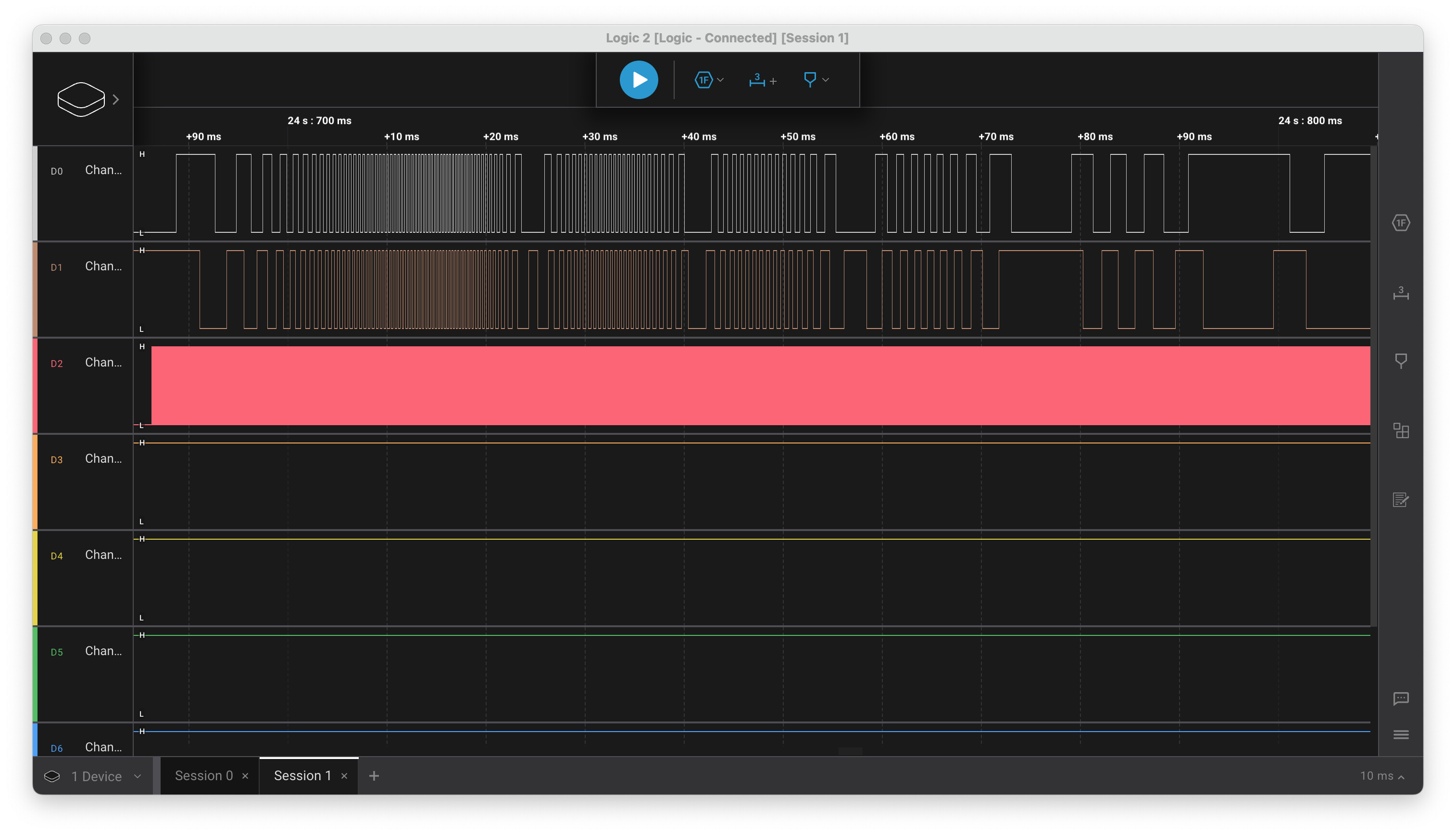
See the logic analyser plot below. I took this while SimpleFOC was doing the motor init.The firt to channels are the encoder A/B and the 3rd is one of the motoer phases. You can see the encoder change directions a few times and it looks pretty clean to me.
THere is a photo of the motor below. As you see, it is easy to count the magnets. Every second magnet has a black stipe on it, I assume they did this at the factory to aid in assemby.
But my test is done at slow speed by hand with no PWM running. Perhaps the PWM and higher currents nearby cause noise? I can add encoder readimng and printing to the open loop test.
I also have an AS5048 and I think I will try that is see what happens. I will need to priint a different test stand
That’s the theory. You could also count the number of interrupts. It would be expected to be 2400 for a full revolution of a 600PPR encoder. If its off by a large amount then there was noise…
But before you invest too much time in this avenue, another cause could be that the voltage is too low during the calibration phase. Of course, on this motor you can’t set it too high either, but the motor has to be able to move well. If it moves by less than the expected amount, then the pole pair check would fail an the reported number of poles would be higher than expected.
Does the motor appear to be moving well during calibration?
I’ve already tried setting the PP to 14 and sure enough this causes the PP test to pass. And I’ve tried setting PPR to 1200, 600 and 300. At 600 I get 6.3 radians per revolution.
I could also count the A/B interrupts in the and see if they match the intended movement. How far does the code try to move the motor? It looks like a large movement followed by two smaller movements with each going in a different direction. I will have to check the source code.
Next I plan on dismantling the encoders and phtogrphing the metal encoder disk and counting the number of slots. The encoder says “600 PPR” but i can’t be sertain how to interpet that. Counting the slots will be definitive. But it is a lot os screwdriver work…
No no, this won’t work. This motor clearly has 7 PP, it’s visible in the picture.
So 600 is the correct setting.
I’d do this in open loop position mode. Leave out the initFOC() so the motor does not move on startup. Initialise the sensor and enable the motor in open loop mode. Set a target position of 2PI and see how many interrupts you get during this motion. It should be round about 2400 (sum of A and B interrupts).
I would not bother. It would be easier to use your logic analyser. Count the pulses on the logic analyser as you turn the motor through one revolution by hand (it should have a mode for counting pulses, or it may even have a specialised encoder mode or gray code mode).
But really, the SimpleFOC code is doing this for you already, so if you’re getting 6.28 for one (hand-turned) revolution then the setting is correct.
I think electrical noise as the motor is commutated is a good candidate, which you could check for with the open loop test.
And/or the motor is not moving well during the alignment phase - this would also explain the bad PP check.
Some possible reasons for not moving well:
voltage too low, so motor can’t move well
current goes too high, so driver switches off due to OC protection - motion is choppy/not normal - usually associated with audible noise
current goes too high, so PSU drops out the voltage - motion is not normal, driver can reset, etc
In open loop the motor turns well with volt limit set to 0.2 volts.
current goes too high, so driver switches off due to OC protection
This has happened in my testing if I set the volts limit too high. It is easy to detect because there is overcurrent LED on the driver board. I have the 8302 progrrammed to shut down, not to throttle
current goes too high, so PSU drops out the voltage - motion is not normal, driver can reset, etc
The voltage limit never allows the power to drop much. I’m using a supply rated at 7 amps and the load regulation is “decent”.
My current theory baased on observing how the motor runs in open loop is “cogging”. Motor.init tries to turn the motor a given amount but the motor will always move in discrete jumps. It either moves zero or one full pole. It does this if I set the volt limit to 0.2 or if I set it so high the motor is too hot to touch. It always acts like a stepper motor, no matter how many or few volts I use. It it is a feature of 12N14P motors?
QUESTION: Can I skip the pole test or can I set PP to 7 after the test and before going into the main loop?
BTW, The PPR number in the constructor has a comment that says this is impuses per rev and 4x the number of slots. I did look at the disk. I literally needed a microscope. the lines were too small to see or count
That is strange. Cogging is definately a common problem, and given the motor has 7PP for its size I would expect it to be a bit “coggy”. But normally, with sine-wave commutation, the cogging doesn’t result in discrete “steps” - its more like unsmooth rotation where the motor is sometimes slower and sometimes faster.
The step-like switching between poles is more what you get when the phases aren’t all working right, or something is wrong with the configuration and the commutation isn’t correct.
What PSU voltage are you limiting to 0.2V?
You can skip the PP check by setting an electrical angle and direction. But if you do this, then you need to know the correct values to set… which is what the alignment is for. So a bit of a chicken and egg problem.