Mosquito Board / New design

That sensor calibration is super helpful. I tried it out, and… it spat out a table of NaNs, but it did at least do a full CW and CCW slow rotation to generate the NaNs :slight_smile: I’ll dig deeper after I try a better jig.

Better jig comparison:

Before (magnet mounted to the rotor directly):

After (magnet mounted to the shaft protruding from the stator):

The magnet is from Digikey, not aliexpress (and not an aliexpress digikey reseller either), so it’s probably OK (it looks like the deadpool logo on a magnetic viewer).

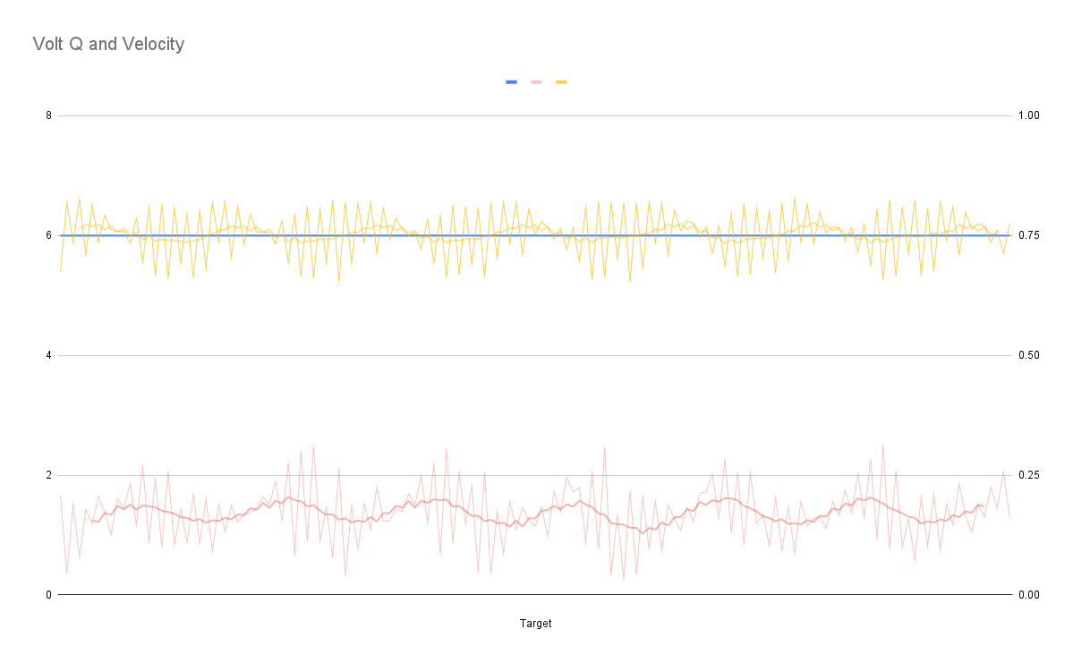
The two graphs show the same time period, with the same settings, just a different mount (and I swapped CW for CCW since that changed).

I think the dramatic reduction in noise is a result of the motor itself not interfering so much with the sensor, but the increase in that clean periodic error appears to be caused by the shaft (2mm, fairly long) wobbling more than I’d like. It could also be that the Mosquito and/or angle sensor are off-center.

The eccentricity calibration is still not working, but I’ll follow up in it’s thread. (Lots of NaN,s and Overflowing floats).

1 Like

I’ve been trying to figure out from the G031 datasheet where this information is given. Currently designing a custom board based on the G071 and I wouldn’t like to make this mistake

I typically use the Pinout configuration tool that comes as part of STM32CubeIDE. This is the main reason I use CubeIDE. It is very useful at working out pin conflicts and chip timings/oscillators settings. I taught myself this tool by following a bunch of youtube vids - Phils Lab is particularly good e.g. this vid.

Here I’ve created a project in cubeide with STM32G071CBU3 mcu and looked at the Timer 1 PWM Generation pins for ch1, ch2 and ch3. They default to PA8, PA9, PA10 but alternatives are available.

The tool also lets you discover alternative pins that can be used with that timer/channel or you could use a completely different timer e.g. Timer3 (PA6, PA7, PB0). You have to spend a bit of time on pinout e.g. PA6 can clash with SPI1 MISO.

1 Like

Thanks a lot.

Do you know if the Advanced-control timer (TIM1) or General-purpose timers (TIM2, 3, …) make a big difference for motor control? Is TIM1 always recommended for SimpleFOC?

I’m not an expert but I think if you are interested in 6xPWM then you may need to stick to Tim1 as it has 6 channels. Tim2 and Tim3 have 4 channels so should be good for 3xPWM.

Just remembered… If you don’t want to use cubeide then you can also look at the appropriate arduino_core_stm32 folder for which ever chip you choose (e.g. G071C(6-8-B)(T-U)_G081CB(T-U)) and in particular the PeripheralPins.c. It is a bit more complex as you have to find pin conflicts yourself.

Also look at the boards and do a search for STM32G071xx to find complete boards that match your chip. I’d advise to make yours similar to one of these so that when you choose that board in arduino/platformio it is ‘compatible’.

For example you may want to make it similar to the nucleo g071rb board (which can be bought for ~£12). You might want to look at it’s schematic and chose a similar external oscillator

This is all at the edge of my knowledge as I’m a hobbyist so cross check.

2 Likes

A neat tool I recently started using is this:
https://github.com/ussserrr/stm32pio
You can use STM32cubeIDE or STM32cubeMX to generate the .ioc file, which has this information about pinout, timers, etc, then it will generate a platformio project which has all the peripherals in their own files/headers. It’s really nice to escape the sluggish cubeIDE.

Actually, since each of the timers also has inverted output, you can do 6PWM with the other timers too (TIM2_CH1, TIM2_CH1N, TIM2_CH2, TIM2_CH2N, TIM2_CH3, TIM2_CH3N) etc. edit: not true for all timers, need to check per chip. This makes the layout a little easier since usually you can put the pins with inverted channel all next to each other too.

I think there is not support in SFOC yet for some of these advanced features. It’s probably a good idea to lay out on the advanced timer, but it doesn’t do anything different at this time yet AFAIK.

1 Like

Hello again!

I managed to make a mosquito board working in “basic experimental mode”: I connected the probe and a serial line, and thanks to the sample repo posted above (“GitHub - josephduchesne/SimpleFoCMosquitoTest”) I flashed it and made the motor turn in open loop mode.
Then my son soldered the sensor for me on the other side and I verified that it works (it reads numbers using SPI and the numbers change if I wave a magnet near it).

Now I am waiting for the proper magnets I ordered to arrive, I’ll design a mounting bracket, and I’ll test it properly.

Meanwhile I wanted to experiment setting up the SimpleFOC Commander interface, and I noticed a weird thing about the Mosquito V2 pinout.

Please, correct me if I am wrong on any of the following:

  • the magnetic sensor is connected to pins A7, A6, A5 and A4 (MOSI, MISO, CLK, CS), which are supposed to be SPI1 pins
  • the post describing the board (one of the firsts of this topic) says that the sensor is on SPI2
  • version V1 of the board has the 12 I/O pins apparently designed to be two independent SPI interfaces, with pins for SPI1 (A7, A6, A5, A4) and SPI2 (B6, B7, B8, A8 as MOSI, MISO, CLK, CS)
  • version v2 (which is the one I have) apparently has B0 instead of A8 (at least according to the labels on the board itself), which means that the “second set of pins” cannot be configured as a “SPI2 port” (and SPI1 is taken by the magnetic encoder)

So the question is: what interface am I supposed to use to control the board?
I was planning to use SPI2 but with the V2 pinout it seems to be missing the CS pin.
What did I get wrong?

Thanks!

1 Like

AFAIK you can use “any” GPIO pins as CS-pin for SPI. You can even use several CS pins on the same SPI bus, so I’m sure they are not hardwired.

1 Like

Yes, @o_lampe is correct, CS is just any GPIO pin, it does not have to be connected to the peripheral. In fact, if you wanted to use more than one device with the SPI bus, it would require you to start using other available GPIO pins anyway.

-----apparently has B0 instead of A8 (at least according to the labels on the board itself), which means that the “second set of pins” cannot be configured as a “SPI2 port” (and SPI1 is taken by the magnetic encoder)

Did you check wh!ether B0 is an alternative CS pin in the MCU? What makes you conclude B0 is the wrong pin?

valentine

Hello Valentine!
And BTW, thanks again for everything you do on this forum and for this project, and thanks to everyone that is helping me.

Did you check wh!ether B0 is an alternative CS pin in the MCU? What makes you conclude B0 is the wrong pin?

Well, yes, I did, and I was pretty sure there was something I did not understand, I hoped it was clear from the way I was asking.

Of course if you designed the board this way there has to be a way to use it, but I did not find a code example to communicate with it so I tried to understand how to do it on my own.

I checked the CPU data sheet from here: “https://www.st.com/resource/en/datasheet/stm32g031j6.pdf” (the link is in the Mosquito user manual, which is super-helpful).

When searching “SPI2_NSS” in the PDF I found it in a few table rows related to pin functions and alternate functions.
In my search I found it associated to rows for pins PB12, PA8, PD0, and PB9.
And when searching “PB0” I found it associated to “SPI1_NSS/I2S1_WS, TIM3_CH3, TIM1_CH2N, LPTIM1_OUT”, but not to the CS or NSS functionality for SPI2.

For sure it’s me, I did not read the data sheet correctly, because apparently the SPI2_NSS functionality in SPI slave mode can be associated to any I/O pin.
And really, this is why I asked :slight_smile:
Note that I am really new to this, I have never used SPI before in an embedded project (all the sensors I used so far were I2C).

All in all: thanks for pointing me in the right direction, I’ll use PB0 as CS in the code and now I know it should work.

I still have to solder the second connector so it will take me a few more days, for now I am bringing the experiment forward on the software side because I want to be sure I can do a build with the Commander that still fits the flash size.
And when I’m done I’ll post a link to my fork of the sample PIO project so others can use it.

So, again, thanks: mine was a honest question because I tried to see how to make it work but I did not understand!

2 Likes

Something that I found helpful for fitting Commander on boards with small (65kb) flash is to compile using the -flto optimization flag. You can put this flag with the others in your platformio.ini file.

Correct.

You will need, however, to explicitly assign the SPI2 to that CSS/NSS pin.

The advantage of the hardware SPI CSS pin is that you can create an SPI object with a shortcut. OTH nothing stops you from using any other pin with some extra lines of code. If you search this forum, there were some examples of code doing that.

Cheers,
Valentine

PS found it, this is an example for a sensor I wrote. Replace the pins with your pins.


#include <SimpleFOCDrivers.h>
#include "encoders/sc60228/MagneticSensorSC60228.h"

// SENSOR SPI SC60228
// SPI2 PINS
#define CSN2 PB12
#define CLK2 PB13
#define MISO2 PB14
#define MOSI2 PB15

MagneticSensorSC60228 sensorSC60228(CSN2);

SPIClass SPISensor(MOSI2, MISO2, CLK2);

// Inside setup {
sensorSC60228.init(&SPISensor);
// }

Does anyone have an updated project based on @Valentine 's recommendations?

Tried to update the board myself to use an available G071 chip but probably ruined it. I made it 25x25 to make my life a little easier. Might give it a second attempt as I have learnt a lot doing this one.

1 Like

I found that chip or a very similar one which was in the lepton to be painfully small/limited . I would recommend you start with the qvadrans, and if you need it to be cheaper, modify that.

Ironically its only £150 for 10 Qvadrans and £100 for 10 of my botched mosquitos. Which really makes it a better deal, but I kind of liked how small the mosquito was to have it sit on the back of a small gimbal motor.

Not sure how you are doing it but you can simply replace the G031 with the G071 during BOM selection, the pinouts of the two footprints are absolutely identical. No need to rework the PCB.

Make sure you select the correct footprint variant, there are two 28 pin G071.

Cheers,
Valentine

Hi

I am a bit new to this.

Checked out your design on oswlab.

Have you managed to get it to work?