Here is the exact code I used, sorry if it is not elemental and as simple as possible, but you can run it the way it is and nothing bad should happen. If you actually use it to drive a motor, make sure you adjust the voltage in various ways, the acceleration etc. as well. It boots up with the voltage_override set to zero, you have to set it to 1 over the serial port for the motor to start moving, otherwise the voltage is zero. Even when it is zero, for me the mosfets get hot. You have to send enough characters over the serial port, 9 including the hard return, before it processes the command, for the commands with capital letters. The small letters read parameters, the capital letters set parameters.
#include <SimpleFOC.h>

// NUMBER OF POLE PAIRS, NOT POLES, specific to the motor being used!
BLDCMotor motor = BLDCMotor(7);
//this line must be changed for each board
BLDCDriver6PWM driver = BLDCDriver6PWM(A_PHASE_UH, A_PHASE_UL, A_PHASE_VH, A_PHASE_VL, A_PHASE_WH, A_PHASE_WL);
LowsideCurrentSense currentSense = LowsideCurrentSense(0.003, -64.0/7.0, A_OP1_OUT, A_OP2_OUT, A_OP3_OUT);
LowPassFilter diff_filter = LowPassFilter(0.05);
float goal_speed =0;
float v=2;
float v_diff=1;
float accel = 92;// in rads per second per second
float v_per_radsPS = 0.0232;
float accel_v_boost = 0.5;// voltage is increased during acceleration and deacceleration by this amount
bool voltage_override = 0;
float power_figure = 1.5;
float power_coeff = 0.00043;// the serial communicator could actually use an extra digit for this one.
float A, B, C;
float currentlf_now =0;
float prop_V= 0;
float min_V = 1;
float v_limit = 19;
float current_limit_slope = 1.6;// this is in milliamps pre rad per second
float current_limit_o_term = 200;//this is the current limit at zero rps, it may not trip with stall
float maybe_o = 1;
void SerialComm(){
  if (Serial.available() > 0){
  switch(Serial.peek()){
      case 't': Serial.read(); Serial.print("t"); Serial.println(goal_speed); break;
      case 'c': Serial.read(); Serial.print("c"); Serial.println(accel); break;
      case 'v': Serial.read(); Serial.print("v"); Serial.println(motor.voltage_limit, 4); break;
      case 'n': Serial.read(); Serial.print("n"); Serial.println(v_diff); break;
      case 'p': Serial.read(); Serial.print("p"); Serial.println(v_per_radsPS, 4); break;
      case 'b': Serial.read(); Serial.print("b"); Serial.println(accel_v_boost); break;
      case 'o': Serial.read(); Serial.print("o"); Serial.println(voltage_override); break;
      case 's': Serial.read(); Serial.print("s"); Serial.println(motor.target); break;
      case 'f': Serial.read(); Serial.print("f"); Serial.println(power_coeff, 6); break;
      case 'g': Serial.read(); Serial.print("g"); Serial.println(currentSense.getDCCurrent(), 5); break;
      case 'i': Serial.read(); Serial.print("i"); Serial.println(get_mA(), 4); break;
      case 'j': Serial.read(); Serial.print("j"); Serial.println(min_V); break;
      case 'w': Serial.read(); Serial.print("w"); Serial.println(driver.voltage_power_supply); break;
      case 'k': Serial.read(); Serial.print("k"); Serial.println(v_limit); break;
      case 'y': Serial.read(); Serial.print("y"); Serial.println(current_limit_slope); break;
      case 'u': Serial.read(); Serial.print("u"); Serial.println(current_limit_o_term); break;
      case 'e': Serial.read(); Serial.print("e"); if (motor.shaft_angle >= 0){
           Serial.println(motor.shaft_angle, 3);
           }
           if (motor.shaft_angle < 0){
           Serial.println((_2PI-(-1*motor.shaft_angle)), 3);
           }
           break;
  case 'T': break;
  case 'C': break;
  case 'V':  break;
  case 'P':  break;
  case 'B':  break;
  case 'Y':  break;
  case 'U':  break;
  case 'O': break;
  case 'F':  break;
  case 'J':  break;
  case 'W': ;break;
  case 'K': ;break;
  default: Serial.read(); break; //if anything we don't recognize got in the buffer, clear it out or it will mess things up.

  }
}
  if (Serial.available() >= 9){
  switch(Serial.read())
  {

  case 'T': goal_speed = Serial.parseFloat();break;
  case 'C': accel = Serial.parseFloat();break;
  case 'V': v_diff = Serial.parseFloat(); break;
  case 'P': v_per_radsPS = Serial.parseFloat(); break;
  case 'K': v_limit = Serial.parseFloat(); break;
  case 'B': accel_v_boost = Serial.parseFloat(); break;
  case 'Y': current_limit_slope = Serial.parseFloat(); break;
  case 'U': current_limit_o_term = Serial.parseFloat(); break;
  case 'O':
    maybe_o = Serial.parseFloat(); // just in case the wrong data gets in somehow we don't want the voltage going crazy
    if (maybe_o < 1){
      voltage_override = 0;
      }
    if (maybe_o >= 0.999){
      voltage_override = 1;
    }
    break;// if it's not one of these, ignore it.
  case 'F': power_coeff = Serial.parseFloat();break;
 // case 'W': driver.voltage_power_supply = Serial.parseFloat();break;
 // case 'J': min_V = Serial.parseFloat();break;

  }
  }
}
void overcurrent_trip(){// if it stalls this won't help except at higher powers, probably. Just helps prevent disaster
  float current_cap = current_limit_o_term + fabs(motor.target)*current_limit_slope;
  if (get_mA() > current_cap){
    voltage_override = 0;
  }
}

void setup() {
  Serial.begin(1000000);
  Serial.println("test serial2");
  // driver config
  // power supply voltage [V]

  driver.voltage_power_supply = 24;
 // driver.dead_zone = 0.1;
  driver.init();
 // driver.dead_zone = 0.1;
  // link the motor and the driver
  motor.linkDriver(&driver);
  currentSense.linkDriver(&driver);
  currentSense.init();
  currentSense.skip_align = true;
  FOCModulationType::SinePWM;
  motor.voltage_limit = 1;   // [V]
  motor.velocity_limit = 255; // [rad/s]

  motor.controller = MotionControlType::velocity_openloop;

  // init motor hardware
  motor.init();
  motor.voltage_limit = 2;
  goal_speed = 2;
}

unsigned long int ticks_diff(unsigned long int t2,unsigned long int t1){ //t2 should be after t1, this is for calculating clock times.
  if (t2<t1){//t2 must have wrapped around after t1 was taken
     return (4294967295-(t1-t2));
  }
     return (t2-t1);
}
float get_mA(){// this is the estimated current being drawn from the power supply, not the actual motor current which is a bit different
   float x =0;
   x = currentlf_now*motor.voltage_limit/24;
   return  1000*((4.0384440932900223e-002)+3.4514090071108776e-002*x*30);// this is off by like 12 percent in some cases a polynomial of third order fits the data better but might flake out at higher than 500 mA so I didn't try it.
}
void loop() {
     static unsigned long int loop_clock_in = millis();
     unsigned long int loop_time = 0;
     float loop_time_s = 0;
//     unsigned long int inner_loop_time = 0;
     loop_time = ticks_diff(millis(), loop_clock_in);
     loop_clock_in=millis();
     loop_time_s = float(loop_time)/1000;
     if (motor.target < goal_speed-(accel*loop_time_s*1.5)){//rps not positive enough
           if (motor.target < 0){//counterclockwise rotation, deaccelerating
      motor.target = motor.target+accel*loop_time_s*0.7;
      motor.move();
      prop_V = (v_diff+accel_v_boost+fabs((motor.target*v_per_radsPS))+(power_coeff*pow(fabs(motor.target),power_figure)))*voltage_override;
     }
          if (motor.target >= 0){ //clockwise rotation, accelerating
      motor.target = motor.target+accel*loop_time_s;
      motor.move();
      prop_V = (v_diff+accel_v_boost+fabs((motor.target*v_per_radsPS))+(power_coeff*pow(fabs(motor.target),power_figure)))*voltage_override;
     }
     }

     if (motor.target>=goal_speed-(accel*loop_time_s*1.5)){//steady run phase
      if (motor.target<=goal_speed+(accel*loop_time_s*1.5)){
        motor.move();
      prop_V = (v_diff+fabs((motor.target*v_per_radsPS))+(power_coeff*pow(fabs(motor.target),power_figure)))*voltage_override; //constant run
      }
     }


     if (motor.target > goal_speed + (accel*loop_time_s*1.5)){ //rps too positive
           if (motor.target > 0){ //clockwise rotation, deaccelerating
      motor.target = motor.target-accel*loop_time_s*0.7;
      motor.move();
      prop_V = (v_diff+accel_v_boost+fabs((motor.target*v_per_radsPS))+(power_coeff*pow(fabs(motor.target),power_figure)))*voltage_override;
     }
          if (motor.target <= 0){
      motor.target = motor.target-accel*loop_time_s; //counterclockwise rotation, accelerating
      motor.move();
      prop_V = (v_diff+accel_v_boost+fabs((motor.target*v_per_radsPS))+(power_coeff*pow(fabs(motor.target),power_figure)))*voltage_override;
     }

     }
     if (prop_V < min_V){
      motor.voltage_limit = min_V*voltage_override;
     }
     else {
      motor.voltage_limit = prop_V;
     }
          if (prop_V > v_limit){
      motor.voltage_limit = v_limit;
     }

     for (int i=0;i<10;i++){ // shouldloop at about 37 khz on b-g431 board
     for (int q=0;q<5;q++){
     motor.move();
     motor.move();
     motor.move();
     motor.move();
     motor.move();
     }
//     Serial.println(micros()-inner_loop_time);
//     inner_loop_time = micros();
     SerialComm();
     }
     currentlf_now = currentSense.getDCCurrent();
     currentlf_now = diff_filter(currentlf_now);
     overcurrent_trip();
}
I think if you just run it with open loop at 2 radians per second with elemental code that should show the problem. Might give you more confidence that it’s not my code in some way. I’m pretty sure it can’t be my code.
I noticed there is a short period after power up when the program is still initializing that the current is more like 50 milliamps. I could probably remove lines of code or stop the program with a delay() to see when the current first starts, but presumably it is when the pwm signal starts going to the mosfet drivers. What is really needed is to poke in there with an oscilloscope with multiple channels. I have a suitable scope but it would be very hard to access the pins esp multiple pins with only two hands… hm maybe I can do it somehow.
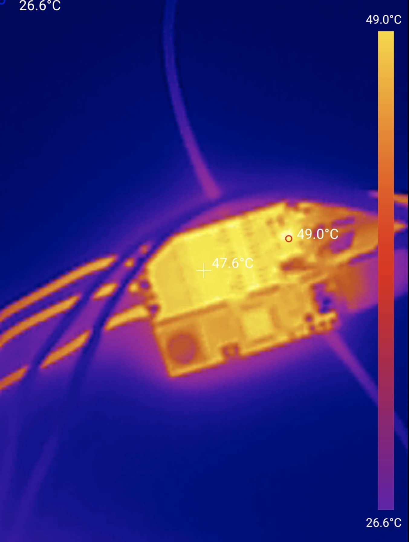
I did a test and the mosfets get to about 90 degrees C when the whole ssystem is consuming 350 mA, which implies about 250 mA to the actual motor. It seems to be stable there though and the mosfets should be good for higher temperatures, so my main concern is that this problem be inhereted by the lepton 3.0, rather than fixing it with this board, but really it should be elucidated as there is definitely something borked here.