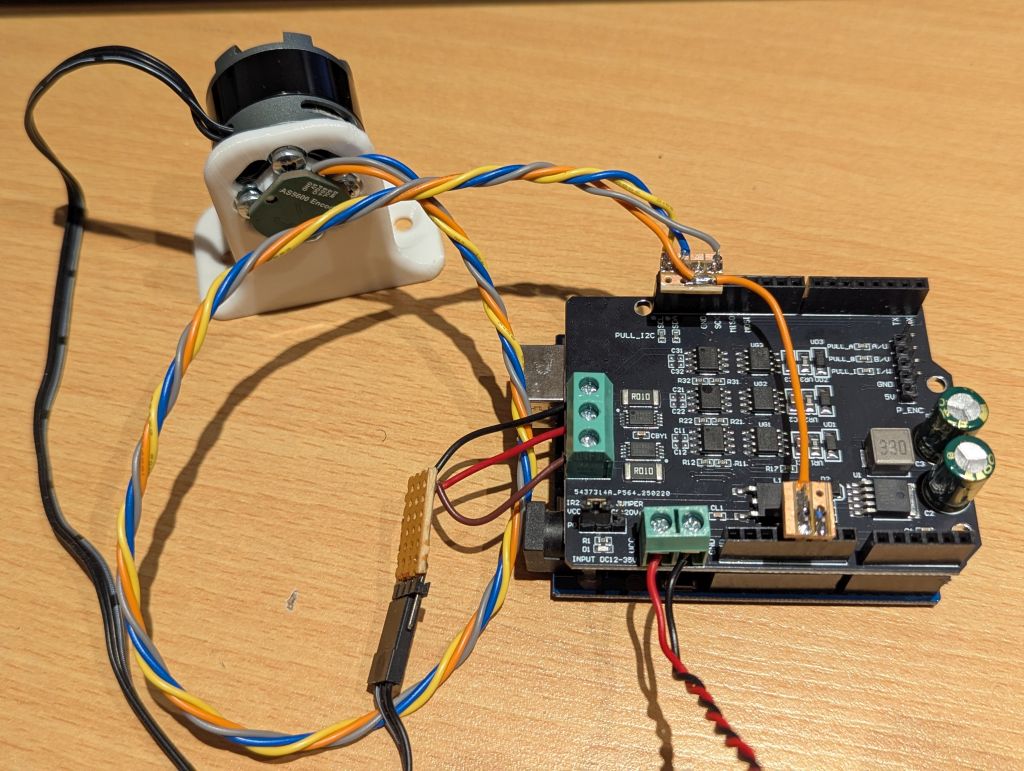
Hello! I am VERY curious about how you got this Shield to function. I struggled with this board for weeks with the help of Claude.ai, all the time thinking that we were having software problems. FINALLY after much consternation I discovered that these driver boards are not functional as shipped from the manufacturer! The bypass and bootstrap capacitors (decoupling and charge pump capacitors) are not populated on the PCB.
These are C11, C12, C21, C22, C31 and C32. EVERY photo I’ve seen of these boards shows these caps missing. They’re only supposed to be 0.1 uF, but without them the MOSFETs cannot fire correctly. The board also has a design problem with the drive voltage for the MOSFETs. There is an 8V regulator onboard, but it should be at least 10V and better 12V. However, you need to be careful going above 12V because this is also Vin for your Arduino board, and 12V is the max for many UNO boards.
I’ve been in the process of purchasing and installing the parts to correct these problems, but yesterday I received another different board from AliExpress. I’ll follow up this post with how it worked for me. Even with Claude’s help I haven’t been able to find any documentation for this board, so today I’m tracing the interface signals from the ESP32 module to the board components. I should know in the next couple days if this is going to work. I’ll let you know as soon as I know.