Dear all
Just wanted to give my two cent on the 3 pin pwm vs. 6 pin configuration.
From a safety point of view, it would be a good idea to stick with the current confiq. and advise on using eg. the MIC4605-2 driver to handle the high side - low side switching with dead time insertion. This will totally offload the library and all future development on many MCU´s. The added bonus is the safety involved in switching relatively high currents. By doing the configuration in hardware. Mosfets will never fry because of poorly written code or lacking flags in registers. Well maybe they will fry because of bad code, but not because the high side and low side on the half bridges crach.
Imo it is more important to focus on the current sensing part, which is relatively straight forward.
Hey @Juan-Antonio_Soren_E,
You are absolutely light that it is safer, I agree. It is also, in many cases, overly complicated. Due to the need of general 2× pwm signals without the adding any new information.
And at the end, it is very very hardware specific. I have spent some time implementing 6pwm mode on stm32 through Arduino IDE and it is an absolute nightmare. 
Even for just specific set of pins. I still did not give up this as an option, but it is much more complicated than I expected. 
In terms of current sensing an torque control. Unfortunately it is also much more complicated than it looks.
The main problem is ironically the sinusoidal pwm. Reading the current data depends a lot on the pwm starte. Is it high or low. And optimal would be to read it on center of the high region.
This means a lot (really a lot) of hardware specific code. It would also mean that Arduino UNO and similar devices would not be compatible with current clntrol, even though they have enough analog pins.
Therefore in a lot of current control applications they use square waves instead the pwm. This allows them to read the current value regardless of the state of the pwm, because there is no pwm.
I am still in the testing pause of this feature and I hope to have it soon, but it is unfortunately much more complicated than I thought. 
Here is a way to filter the pwm current measurements. By calculating a moving average.
Have you tried this approach in your design ?
https://www.baldengineer.com/measure-pwm-current.html
Hola Juan,
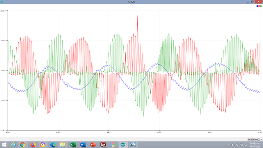
Thanks for the input. I read the article you shared and it seemed very easy to implement to my hardware so I did a quick test. Both tests were running angle position control and moving the rotor with my hand.
These are the measurements of phase current raw from the ESP32’s ADC.
This picture shows one phase (blue) with MMA applied with 20 samples:
Maybe you’re onto a not-so-harware-specific solution, I’d like to hear @Antun_Skuric’s take on this solution.
Hey guys,
Yeah this is one of the solutions, I agree.
MMA algorithm is basically this:
current_filtered = (N-1)/N*current_filtered + 1/N*current_measured
This is a very simple low pass filter algorithm. I would prefer to use the LowPassFilter class of the SimpleFOClibrary because it doesn’t depend of simple times. But I will definitely test this properly and I’ll give you the updates.
My fear is just that these kinds of algorithms are not taking in account the dynamics of the current in the motor and that they will not be suitable for real time control of the motor. But they are probably going to be enough for torque control (take max value of current for example) but maybe not FOC ( controlling Id=0).
As a remark, I also tested the average several measurements of the current:
current_measured = (analogRead(.) + analogRead(.) + analogRead(.) + analogRead(.) ) /4
for example. This will sample the current in 4( this number can change ) random moments of the highs and lows of the PWM. But the good thing about this approach is that it doesn’t introduce phase shift of the sine waves as does the low pass filter or MMA.
The problem of this approach is that it requires much more time to execute.
But still I was not able to get good results with either of the two or their combinations. There is some work to be done here. 
1 Like
I actually went with the MAX40056. I like the ruggedness of that sensor. It lest the MCU focus on other taskes. I have great hopes for the SAMD(E)51 120mhz. This is also a case study, of how to implement this sensor. I have been doing work on a 300 amp controller, where this kind of current sensor might fit well. The general idea of THE DIMMER design, is for the board to be sitting berry close to the coils. Maybe the BOM count and cost goes up a bit, but IMO its still within reason.


