I am writing a program to measure the series resistance of the motor in the static condition. The idea is i give a 100% duty to U phase, the V and W phase i give 0% duty. Then the motor rotates and stops at a position. I measure the feedback current using current sensors. I am not sure if i give 100% duty all the battery voltage will be applied to the U phase, i think a voltage of Battery Voltage / Sqrt(2) will be applied to the phases. Hence the resistance is
R = Voltage applied to Phase / Feedback current. Please help if the algorithm is correct.
I think at 100% duty cycle you will burn the phase.
Controllers like vesc can do this because it also measures the phase voltage.
I mean can i set around 70% duty etc i want to vary and test.
You can only do this for high resistance motors. On a low resistance motor the current will rise too high if you allow DC current to flow through the windings.
If you open the high side FET and allow DC current to flow through the windings on a high Ohm motor, the winding will see almost the battery voltage. There will only be a small difference due to the voltage divider formed by the MOSFET RDSon resistance, the winding and the low side MOSFET RDSon.
There is no factor of SQRT-2 for the DC Voltage.
The current measurements together with the known resistance will allow you to calculate the phase to phase resistance. Keep in mind the actual phase resistance will be a different value depending on whether the motor is delta or Wye winding type. If you connect one phase to battery voltage, and two to GND, then you can consider the parallel resistances of the two grounded windings when doing your calculations.
But the problem is when i do this algorithm i will not be knowing if it is high resistance or low resistance motor. Can i start from low duty and slowly increase the duty and find the difference in currents due to the change in the duty and measure the feedback currents?
Also i want to measure the inductance how do i do? Any suggestions.
Hi,
delta_U / delta_I is the safest method to calculate the resistance.
As you wrote, start with a low voltage/PWM => measure the resulting current.
Based on that current, decide how high you can set the second voltage.
The further apart you can set the two voltages, the better. (without exceeding current limits)
Quite honestly, with only the possibility to measure current, and no known quantities to work with, I think it might be difficult.
I would be very interested to hear people’s suggestions. I think we can regard the question to be:
“How do I characterise a motor, given only normal driver hardware?”
We’d like to find the pole pairs, winding resistance, inductance, and torque constant of the motor so we have all the parameters to drive it well.
@o_lampe 's suggestion is obviously the way to start, but I am not sure it will be precise if you have only current measurement, and no voltage measurement. I am not sure how well the assumption holds that the winding voltage is exactly the DC voltage scaled by the PWM duty cycle, or whether your measurements will be the same if you use 1kHz vs. 100kHz PWM.

I think you ultimately have to have a close look at all the equations. I was thinking measure the rate of rise of current to get the inductance, but I think it might be influenced by the resistance.
You could change the frequency and detect the variation of current with frequency, that should reveal inductance.
The motor control workbench for the b-g431b-esc1 board has a very interesting motor characterization program, it was able to characterize my little gimbal motor and even reported the rotor inertia and all kinds of stuff, it appeared to agree very well with my other measurements. It reported KV rating and all kinds of stuff. It’s supposed to be open source, but I think that’s BS. The C code is itsself machine generated. It might as well be assembly.
It would be really cool to have a system that automatically got the motor parameters and then used HFI or similar to jump in to controlling the motor just like a servo motor. All software and existing electronics. That that is possible is pretty amazing, with software we could nearly obviate the magnetic sensors commonly used. However it could never know the absolute position…unless maybe very minute variations in parameters that occur only once per revolution could be detected and used to give the step that the motor is currently at, and then combined with other info to give the actual absolute position :).
That would be nice… honestly sensors introduce a lot of imprecision, too. Because no sensor misalignment or bias is possible I think this approach could actually give a fairly good little servo motor, potentially. You’d need a good little initialization dance to get good data, save the data so you don’t have to do it every time…
I think that is correct, the voltage always goes through 2 phases, not one. This is I think already factored in in simplefoc. Some motor controllers you have to put in that data, the texas instrument one you had to enter that data manually, it had an automatic measurement thing but it didn’t work. Different controllers use it differently, for the TI chip it was phase to phase resistance that you needed to know, in SimpleFOC it’s terminal to terminal resistance i.e. two phases at once. It’s simpler in some ways but could confuse someone with a motor that could be used in either delta winding or wye mode. In delta mode you can arragne things so that the voltage does go across only 1 phase at a time, or you can use the motor in WYE mode. However that bridge can be crossed when we get there, almost everybody here uses wye motors so I don’t think we have to worrry about that.
There are similar complications when calculating the KV rating and inductance, you have to remember you have two phases in there not one.
Maybe the application note AN4680(PMSM Electrical Parameters
Measurement) is useful.
And I came across this implementation based on the paper(Experimental Evaluation of PI tuning techniques for field oriented contol of permanent magnet synchronous motors), it should help derive the PID parameters for current and speed control from the measured motor parameters.
That’s a great reference!
„ but instead of a fixed voltage, it applies a square wave voltage centered about 0 across the D axis. That way the motor doesn’t move, the net current is 0 over time, and the average rate of change can be integrated over many cycles for much higher accuracy.“
That seems to me exactly the way to do it!
Another way might be to increase the frequency of the square wave until it becomes smoothed out, and check when the peaks no longer reach a certain level.
Have to think about it, but something like that might avoid having to measure a delta altogether.
I am wondering if it’s worth investing in a Der EE DE-5000 LCR meter.
So far I have been using Resistance and Inductance values I have found somewhere on internet for hoverboard motors, but there are many types of such motors.
I have a 4.12 Vesc but I am not sure how accurate the resistance/inductance measurement is.
I got this one and it seems to be fine. $23. https://www.amazon.ca/gp/product/B0B9XTK27J/ref=ppx_yo_dt_b_search_asin_title?ie=UTF8&psc=1
We all know the electronics are not super expensive at a fundamental level :).
As I mentioned you can use an oscillocope but I forget or maybe never figured out quite how to do it. You use the test signal.
Maybe a resistor across the inductor would help, that would allow current to flow backwards across the resistor when the voltage from the test signal collapses. How fast the voltage from the inductor decays should give quite an accurate value, you could check it with some discrete inductors.
Just a few bucks more will get you something that looks a bit more solid ![]()
That’s way cheaper than the model I selected (+100euros).
Those are the values I currently have.
Phase Inductance = 0.00036858H or 0,36858mH or 368.58uH
DE-5000 can measure 0.001uH. That’s very precise.

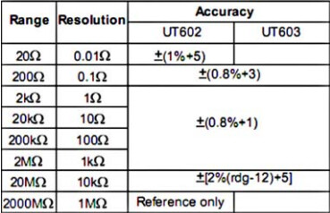
UT603 can measure 0.001mH, that should be enough.

Phase Resistance = 0.1664Ω or 166.4mΩ
Shunt Resistance (RDSON) = 0.008Ω or 8mΩ
The DE-5000 can measure 1mΩ. It’s ok for phase resistance. A rough estimate for shunt resistance.
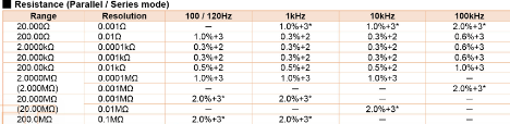
UT603 can measure 10mΩ. Could give an estimate of phase resistance but won’t work for shunt resistance.
I’m sure it’s good to know all the elctric data, but still missing is the rotor inertia IMHO.
At least for a virtual PID tuning model, or not?
Based on the paper/implementation I linked, the rotor inertia is useful for the speed control PID parameters
There is such a thing as autotune for PIDs, there are some arduino libraries but I was never able to get them working. I think it’s a good idea in general as tuning pids can be a real drag and the parameters can change in the field. As you note, the inertia of the rotating component can change optimal pid parameters. Well, that can include the load. The thing is that if it’s not tuned right you can get quite harmful oscillations and that can be a serious problem, so it worries me to release a product into the wild which under some circumstances, which are hard to predict, it could oscillate like that. I think some kind of thing that at least detected oscillations and reduced gain, so a crude auto tune, would be a good idea.