So it seems your previous results are invalid as you probably didn’t trigger the scope at the point where the MCU reset happened. I can help you with how to use the oscilloscope correctly so you can provide the correct measurements next time.
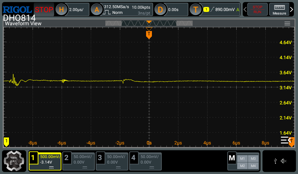
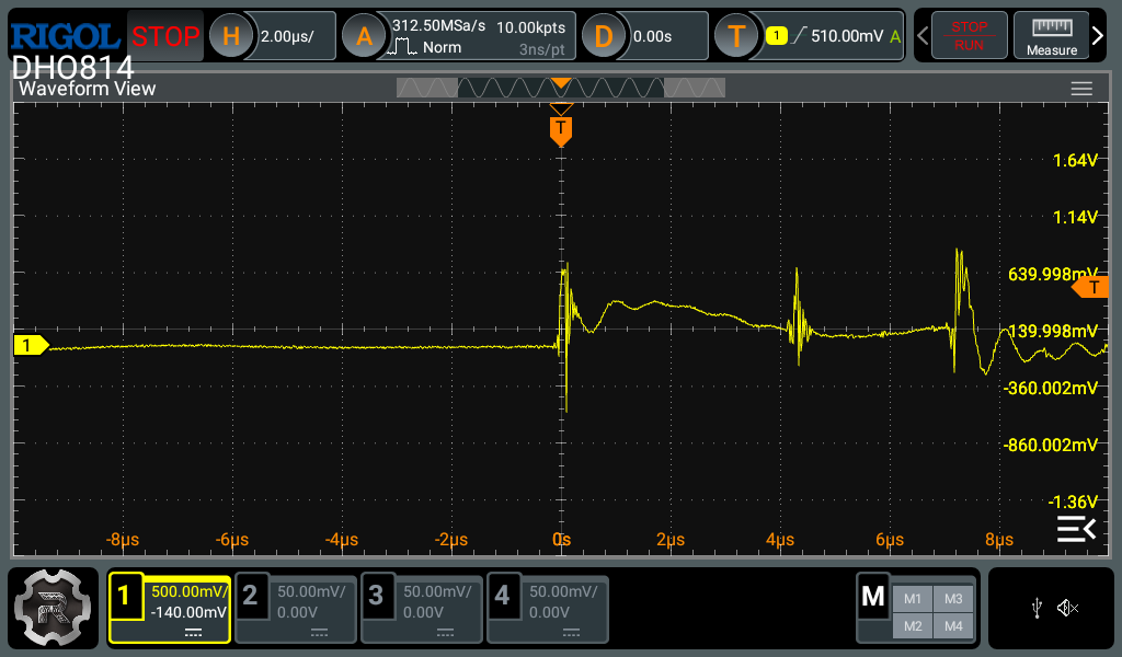
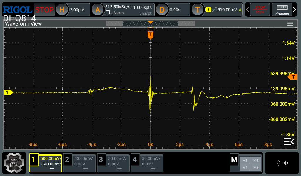
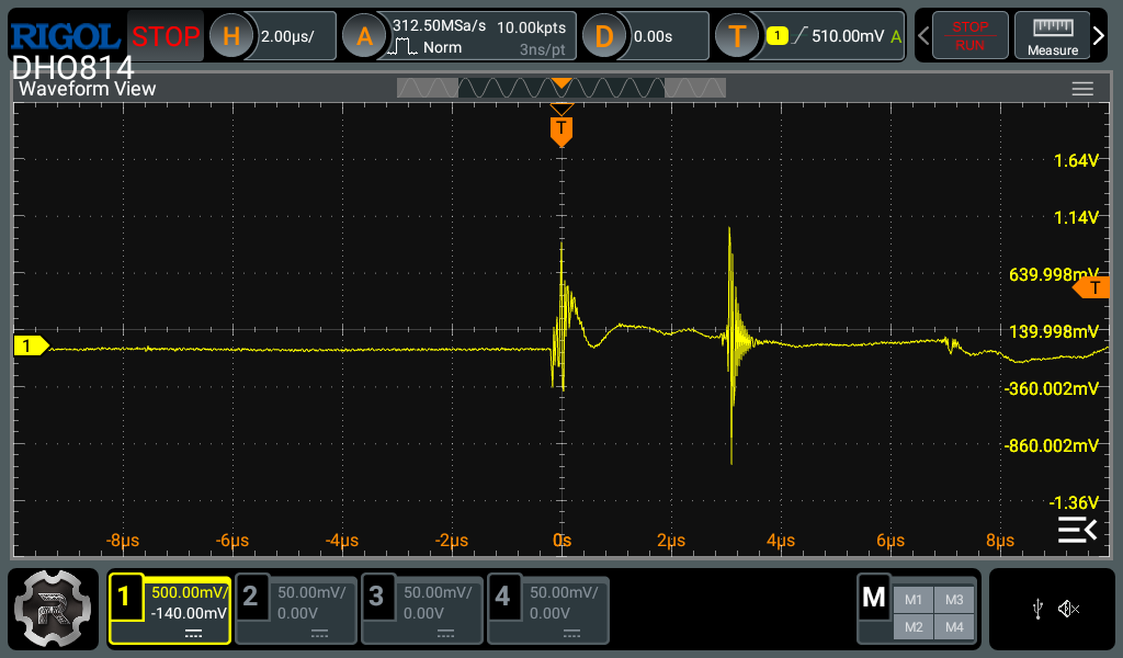
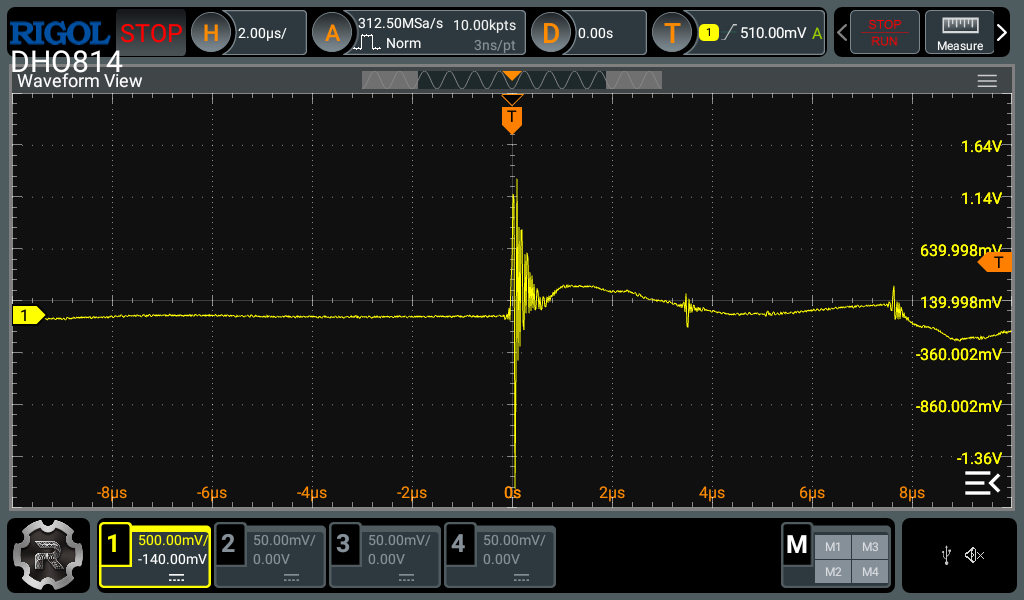
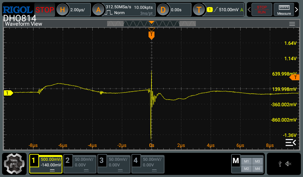
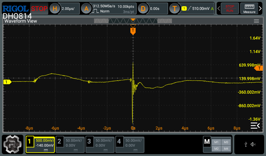
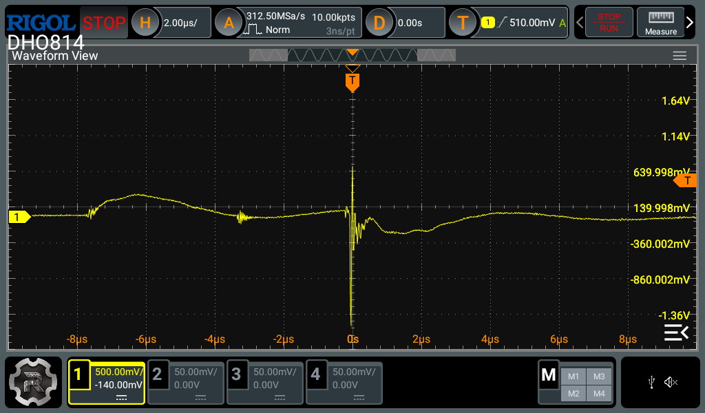
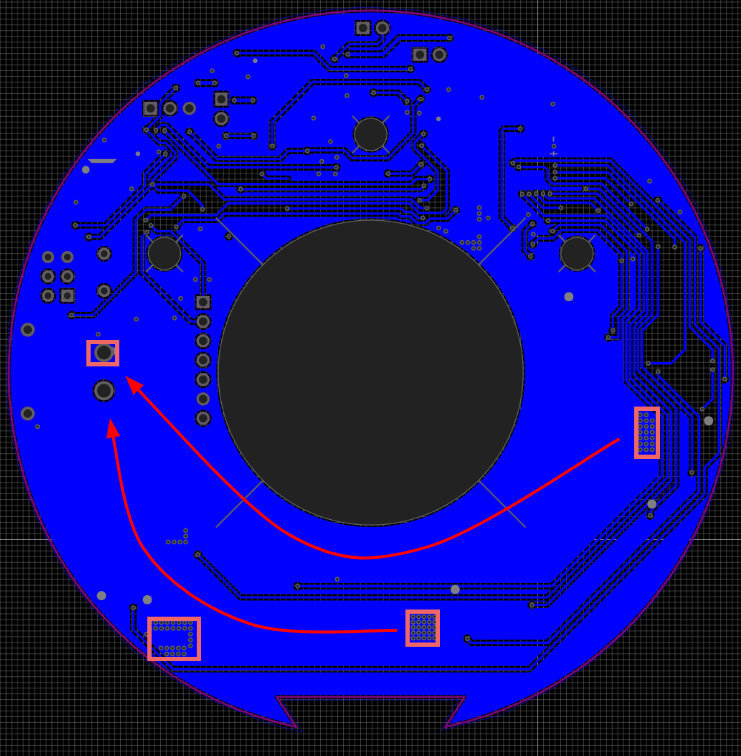
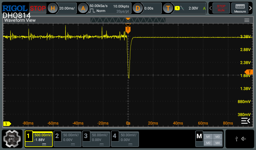
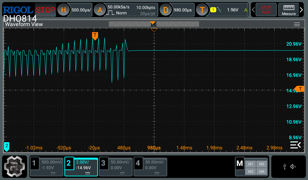
There are 2 main things you need to do to capture the correct region of interest. The first is the vertical settings. You should be setting the gain (volts per division) and offset settings of the scope before the measurement so that the signal always stays fully on the screen. You can usually take a guess at this, and if your guess was wrong, adjust and re-measure. Once the measurement has been acquired, most scopes will still let you change these settings, but it will re-use the existing data which might be affected by clipping / quantization and therefore be inaccurate. I suspect you may have adjusted the offset after the measurement in your most recent screenshots, as the bottom part of the waveforms look unusually flat. Always re-measure after changing the scope settings to avoid this.
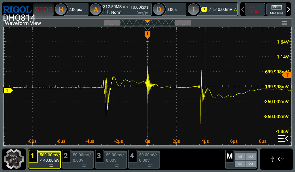
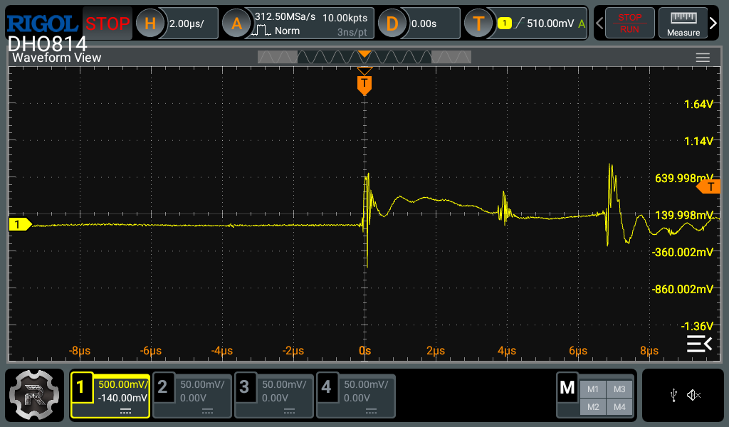
The second is the horizontal settings. Most modern digital oscilloscopes have a decent amount of memory to capture a lot of data in the horizontal axis, unlike the vertical axis. Therefore you can zoom in quite a bit in the horizontal axis before experiencing any artifacts caused by lack of data points. For single events like this, I usually go and set the memory depth to the maximum and use the biggest timebase which still maintains an acceptable sample rate (around 10x the highest frequency you expect to measure). This strategy gives the best change of actually capturing the event and what happened before and after. After the event is captured, you can then zoom in to the interesting parts to see the details.
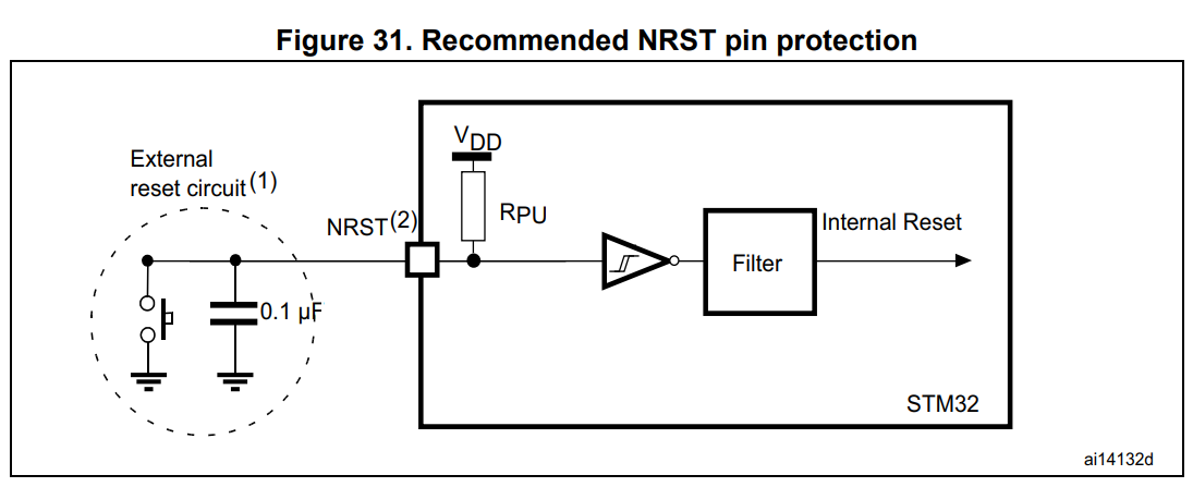
Since scopes don’t have infinite memory and even if you have a very large memory you don’t want to look through millions of data points, scopes come with a trigger feature which helps start the measurement at the correct time. The most common trigger type is an edge trigger, which starts the measurement when the voltage level crosses the trigger level, rising / falling or both depending on setting. The scope can also capture a bit of data before the trigger event. To set the trigger correctly, you want to identify which voltage will change significantly to cross a threshold around when the event of interest occurs, but doesn’t cross that threshold frequently when the event isn’t happening to avoid capturing uninteresting events. This varies case by case and requires a bit of thought. In your case, based on the readout from the RCC CSR register you can probably assume the power rails are a good candidate for the trigger. Another option is to create the trigger source yourself by toggling a spare GPIO pin of the MCU during boot, and using another channel of the scope to trigger off that.
Finally there is the trigger mode which has 3 options. AUTO means it will capture new events if the trigger condition hasn’t been met for a while, and capture on valid trigger events. NORMAL means capture on trigger condition only. SINGLE means capture on first trigger condition and ignore subsequent ones.
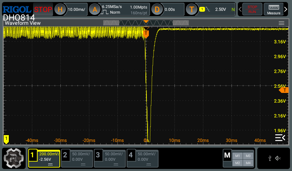
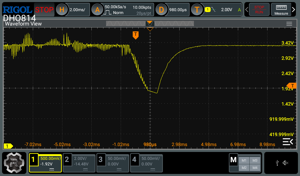
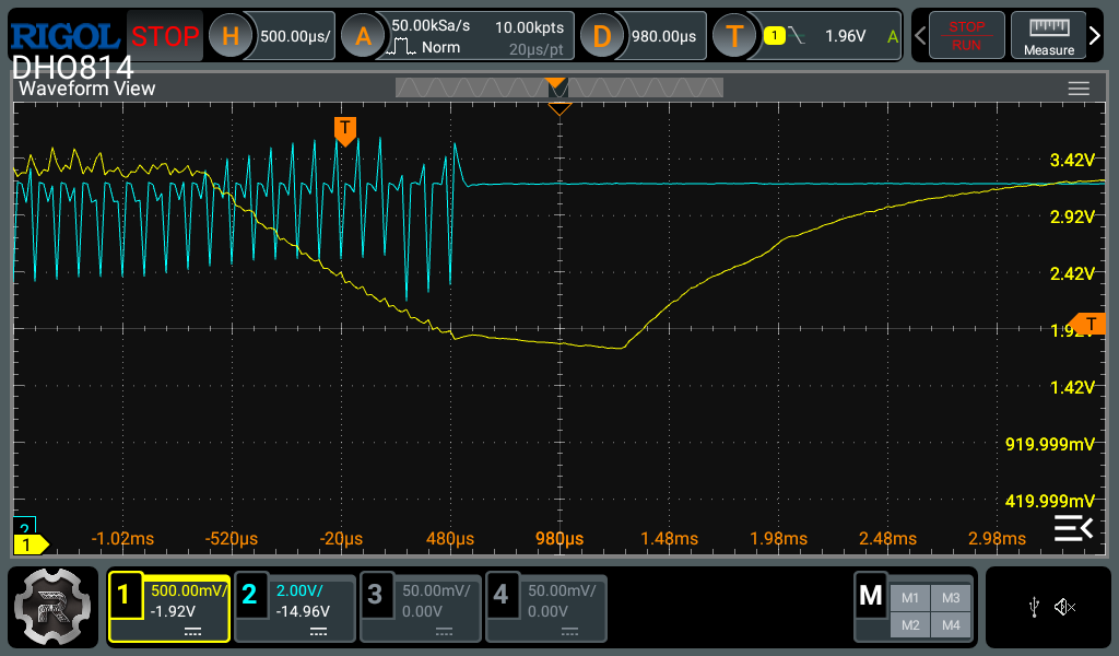
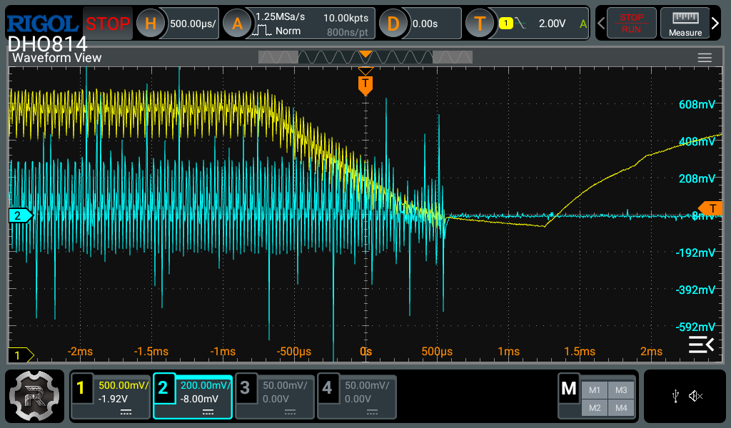
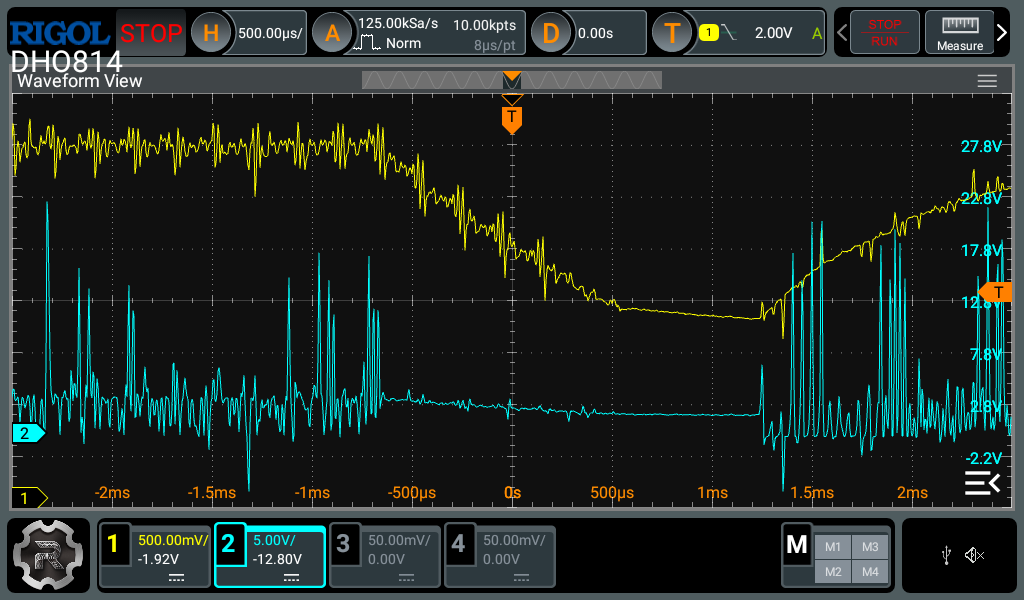
For this case it’s best to use the SINGLE mode, with the trigger set to falling edge with the trigger level at 2.0V, on the 3.3V rail signal. Use the other channels of the scope with more probes to capture the other signals of interest, keeping the first probe on the 3.3V rail signal (otherwise you lose the trigger). Keep in mind that the GND clips on all scope channels are shorted together. Start with a 1ms/div timebase and zoom in if you see anything interesting (especially near the start of the voltage dip).
You can also try and measure the 3.3V output across the DRV8302 buck output capacitor (use the negative of the capacitor for the GND reference) and see if there’s a significant voltage drop there or whether it’s localized on the STM32. Also the switch node of the buck might be interesting to look at (need to zoom in for that one).