Jerky motion open loop with a gimbal motor, arduino nano and L298N

Hey everyone, I am still trying to build an open source energy recovery ventilator (openerv.org). I need quiet motors, with precise RPM control.

I can use the included open loop library example to control the motor’s rpm, as a demo. I got the wiring from this thread, there is none included in the example https://community.simplefoc.com/t/3-bldc-and-stepper-foc-driver-l298n/296/45

But as the video shows, it is very jerky. Any ideas on how I can get smooth motion? It is quiet, though. https://drive.google.com/file/d/1TM7Z1hcQRhO5YeksKZCLbeHRdPiJlpsH/view?usp=sharing

This is the code I used:
// Open loop motor control example
#include <SimpleFOC.h>


// BLDC motor & driver instance
// BLDCMotor motor = BLDCMotor(pole pair number);
BLDCMotor motor = BLDCMotor(11);
// BLDCDriver3PWM driver = BLDCDriver3PWM(pwmA, pwmB, pwmC, Enable(optional));
BLDCDriver3PWM driver = BLDCDriver3PWM(9, 10, 11);

// Stepper motor & driver instance
//StepperMotor motor = StepperMotor(50);
//StepperDriver4PWM driver = StepperDriver4PWM(9, 5, 10, 6,  8);


//target variable
float target_velocity = 0;

// instantiate the commander
Commander command = Commander(Serial);
void doTarget(char* cmd) { command.scalar(&target_velocity, cmd); }
void doLimit(char* cmd) { command.scalar(&motor.voltage_limit, cmd); }

void setup() {
  pinMode(8,OUTPUT);
  digitalWrite(8,LOW);
  // driver config
  // power supply voltage [V]
  driver.voltage_power_supply = 12;
  // limit the maximal dc voltage the driver can set
  // as a protection measure for the low-resistance motors
  // this value is fixed on startup
  driver.voltage_limit = 6;
  driver.init();
  // link the motor and the driver
  motor.linkDriver(&driver);

  // limiting motor movements
  // limit the voltage to be set to the motor
  // start very low for high resistance motors
  // currnet = resistance*voltage, so try to be well under 1Amp
  motor.voltage_limit = 3;   // [V]
 
  // open loop control config
  motor.controller = MotionControlType::velocity_openloop;

  // init motor hardware
  motor.init();

  // add target command T
  command.add('T', doTarget, "target velocity");
  command.add('L', doLimit, "voltage limit");

  Serial.begin(115200);
  Serial.println("Motor ready!");
  Serial.println("Set target velocity [rad/s]");
  _delay(1000);
}

void loop() {

  // open loop velocity movement
  // using motor.voltage_limit and motor.velocity_limit
  motor.move(target_velocity);

  // user communication
  command.run();
}
Also, the heatsink of the driver gets hot even when the voltage is limited to 3 volts, especially at higher rpm. The whole system is only drawing 120 ma and the heatsink still gets hot. How am I going to get smooth, quiet motion…

It’s not the number of pole pairs, I had it wrong, it was set to 11, and it is actually 7 for this motor, but setting it to the right value changes nothing. As you would expect, I guess. It’s supposed to feed 3 sine waves 120 degrees out of phase to the motor, right? It’s not doing that.
shit.
I looked at it with my basic oscilloscope, and the output from the H-bridge is clearly square wave, not being smoothed out, at about 27 khz, which is apparently fine as I cannot hear it.

If you lower the time-sensitivity (h axis) of you’re Oscilloscope, you should see the square wave patterns (the PWM) dissappear, and eventually something like the sine waves should appear, if things are working right.

This should not make much difference for open loop mode

I guess it is losing most of that to heat then. You could try lowering your PWM frequency to 5kHz and see if this helps.

I don’t think I can get away with lowering the pwm frequency because it would produce an audible whine, though I could try it.

Tried changing the time sensitivity, but my oscilloscope sucks, it gets a very low refresh rate on the screen when there are a lot of data points, and as a result I can’t see anything. It’s the open source oscilloscope DSO Quad. Unfortunately open source is sometimes an excuse for poor qualiity…I’m trying not to repeat that mistake.

Yeah, I didn’t think the pole count would make much difference, it just affects the speed of the motor, wave frequency.

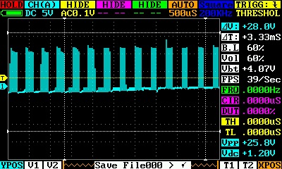
IMAG000
I managed to get the oscope to give me a bit of data. This is one of the phases of the motor. If I make the time period any longer it doesn’t work, it starts freezing, even with scan as the trigger (which is basically just to watch and plot the voltage with time periodically).

You can see there is definitely something wrong. The voltage drops to nearly zero for 250 microseconds every 500 microseconds for one of the phases. That can’t be right. It’s supposed to be approximating a sine wave, right? IDK. I have a teensy and a raspberry pi pico, maybe there is something wrong with the library that would be circumvented if I use another board.

That is set to 10 radians per second velocity

Got it working the same on a teensy 4.0. Same problem. The output waveform is not at all what it is supposed to be. Unless it’s my oscope that is borked. I think I should be using 6 pwm, too, I don’t see how this is supposed to give a sine wave which sinks and sources current with any reasonable efficiency. The half of the hbridge either connects to high or low at any given time. Thus, it will both sink and source current at any point of the wave, which is very inefficient. It should be connected to ground with a varying duty cycle for some periods, and connected to high with a varying duty cycle for some periods. Instead it is constantly flipping from high to low. Very energy inefficient in any case.

Maybe it’s just going low for that period where it is supposed to sink current, that would make some sense. That chops off half the sine wave for each phase, which would explain the jerkiness. This definitely should have been mentioned somewhere. The whole point of FOC is smooth motion.

Well, I would say the way the PWM works is quite standard for motor control…

I think the problem is more using the digital scope to look at something that inherently quite analog. The PWM voltage stands in for an analog current, the motor is an inductive load that acts as a filter to smooth this PWM. To better see what is going on you would either need to measure against the “centre point” of the motor winding, or make a differential measurement across an inline current shunt (resistor) to measure the current directly.
Don’t forget you’re looking at one phase here, and you’d have to look at all three to see the resulting commutation pattern - you can think of the current as flowing in through one FET, through the motor’s windings and out another FET, the FETs switching in such a way that the motor’s windings are always “between” VIN and GND.

The L298N is just an inefficient driver - it doesn’t even use FETs but transistors, and therefore you can expect it to get quite hot.

10rad/s on a 11PP motor is 110 electrical rad/s, or 110 / (2π/3) =~ 52.5 steps of 120° per sec
If I have that right. So you’d expect to see a commutation pattern (the sine waves) at divisions of about 20ms - 100ms on the time scale, but you might have to use a PWM mode or something like that on a digital scope.

But none of that explains why the voltage is zero half the time. I measured the pins at the microcontroller, too, and it is the same story.

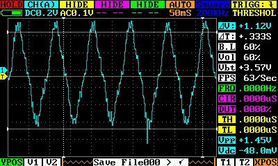
IMAG0002
I connected 3 resistors, 3 ohms each (which is a bit high but it’s all I had), to each of the phases (just to balance the resistance between the phases) of the motor. This is what the oscope reads at I think 6 radians per second of the motor on one of the phases. So it’s not exactly a sine wave, but it doesn’t really explain the jerkiness.

IMAG0003
That’s what it looks like when I command it to raise the voltage to 12 volts through the serial interface. I think that was 5 radians per second. So not exactly a nice sine wave. The peak current is somehow about the same, too, although the power supply indicates it does go up.

Is the wave typically like that? Any ideas? I can’t figure this out. I ordered a mosfet board to try implementing the 6 pwm approach. But I don’t have a lot of confidence in the library at this point. I mean, this is the recommended hardware and a very typical setup, and here it is not working at all, and I can’t get it working.

I have had so many problems with errors and bugs in arduino libraries I don’t hesitate much to assume the problem is with the library, although that might be unfair. The first two PID libraries I tried both had major bugs in them, only the third even worked at all, for instance…

Hey @Anthony_Douglas ,

I am sorry to hear about your problems with the library. Please do consider making github issues once you have a problem and consider making pull requests if you have some good solutions to them. That way you can help others not to have the same issues and you’ll get some deeper knowledge about the algorithms and the library code.

Your osciloscope output seems fine.This is the output for the pwm frequency of 25 kHz or for the default frequency in the library?
Is this the arduino (32 kHz default pwm) or some other board (25kHz default pwm)?
If you are using a board with 25KHz pwm frequency the duty cycle will be 400microseconds and that is exaclty what you are seeing in your osciloscope.

The voltage should not be approximating a sine wave. The voltage is always a PWM signal which is square and it should stay that way. Current that is induced by that voltage will be sinusoidal, that you’ve demonstrated nicely later on, with the resistor. Where by measuring the voltage over the resistor you’ve measured the current waveform passing through the resistor.
Now, if your pwm frequency is not 25Khz then you have an issue. If it is 25KhZ then the waveform is perfectly correct.

This is a nice experiment. The noise that you see at the sine waves is probably the issue that is causing the jerky motion.
In my opinion the issue is related to the raise and fall time of the L298N driver. Is is very long more than 2 microseconds. As typical bldc driver board has rise times of less than 100 ns, L298N is 10+ times slower than regular boards and will need that much lower PWM frequency.

We have had similar issues with BTN8922 and BTN7960 who are as well DC motor drivers and have very long rise times. This doesn’t matter for DC motors but for BLDC motors produces the beaviour you’re seeing.

So in order to try to make repare the behavior, there are few ways you can opt going:

  1. Remove the driver.vlotage_limit if you are setting one. This parameter reduces even more the PWM duty cycle length and can maybe be one of the factors in your case
  2. close the loop: use the position sensor and velocity control. In this way your sensor will see the oscilations and the motion control will account for them
  3. use lower PWM frequency. Use the teensy or Rpi Pico and use driver parameter the driver.pwm_frewency parameter to lower it to some value where you dont see the oscilations any more. If you hit the audible range before you remove the oscilations then you need different motor driver.
  4. use a different BLDC driver. Use a board that has dedicated BLDC driver chip. It will cost you a bit more but you’ll avoid these kinds of issues.

This is also interesting as an experiment. In this case you have very nonlinear current profile. This could be caused by the same problem. But it can be also caused by the saturation of the PWM signal. You are setting a 12V voltage limit, and what is the power supply voltage you’re using for this experiment?
What is the driver.voltage_limit that you’re using in this experiemnt?

The power supply voltage was 12 volts. The driver.voltage_limit = 6 .I Had forgotten about that feature, I thought when I set it through serial it would go up more, but I guess this explains why the current did not rise. The voltage was set to 5 volts in the previous experiment, and in this one it was set to 12 volts through the serial, but the driver.voltage_limit = 6 would have limited it to 6, so nearly the same voltage.

I ordered a board with N-channel mosfets to use in either 3 or 6 pwm mode, to keep trying.

I will try removing the v driver.voltage_limit = 6 or rather setting it to 12 volts.

The oscope grabs you quoted are both from using the teensy, so I guess 25khz. So at least that part is ok.

I would like to use an encoder, but they are way too expensive. They are like $40 each or something, I don’t know why they are so expensive. I need two to four motors. I could use an encoder on just one motor and let the other one stay open loop.

I looked into other bldc boards, but they are just all so expensive and hard to get, that’s the thing. I am faced with brewing my own with the mosfets and mcu and simplefoc as the only practical option. If only these $6 esc things would work with this motor. I have some that work, but only at a single fixed rpm which won’t do.

I looked into adjusting the pwm, but I could not figure out how to do it. Now that you have mentioned the driver.pwm_frequency option I will try that to at least diagnose what is happening.

I tried a sensorless motor control board that uses square waves today, $14 each. however it won’t do, as I expected it is too noisy. I have to have sinusoidal drive somehow.

Thanks for helping, Antun.

Hey @Anthony_Douglas

I’ve tried the setup myself today and I don’t have good news.
I was not able to remove the jerkiness in the openloop even with very low PWM frequency. It gets better but its still jerky.

What is the velocity range you are looking into?

Building your-own board is a good option for sure. N-channel mosfets will work well if you connect them well.
And there is a learning curve there and if you’re anything like me, it might include some burned ones :smiley:

BTW. we do not have sensorless control implemented yet. I’d be in to collaborate on implementing backemf or sensorles FOC but so far we are not concentrating on it much. :smiley:

Hey thanks so much for the test, Antun. I owe you one. At least now it’s on the forum here for the next person that is thinking of using this driver.

There are some people that have implemented sensorless drivers with arduinos, using the analog input of the arduino. I suppose they probably got relatively low rpm, but I don’t know.

I am trying to get 1500 rpm or so out of the motors, at the high end, and maybe 200 at the low end. The KV rating for the motors is suitable for this. The sensorless board I just tried the motor with got 3120 rpm, measured with a laser tachometer.

So, I will wait for the mosfet boards. They should arrive in a day or two. These are the boards, I need 6 mosfets so I would have to use both boards, which is $23 plus tax, which is a bit high, however in production I can just use the mosfets for a dollar each plus the drivers but that’s still not likely to be economical as I have to pay for the assembly time etc. https://www.amazon.ca/gp/product/B07YKFR72R/ref=ppx_yo_dt_b_asin_title_o01_s00?ie=UTF8&psc=1 More likely I would buy mosfet boards from aliexpress. The SimpleFOC board is $30 Cad anyway, plus shipping. which is definitely pushing it. It might be the way I have to go. I do appreciate that it is there and it is fairly inexpensive for what it does, I was just planning on using those cheap l298 boards for $3, $3 each for the motors, that would be an achievement that is affordable to people.

The way things are going my ventilator is going to cost 600 bucks at least after everything and although efficient isn’t particularly quiet anyway. A lot of people can’t really afford that, but I can only do so much. The nearest commercial option is $1100 CAD after tax and shipping, the purifresh. It’s the only other unit that can go in a window. That’s a lot of money just for some fresh air. My only real hope to get the cost down if things keep going the way they are is to offer kits.

Hey, just read through this thread. Did you end up being able to spin your motor in open-loop with reduced jerkiness? Did you use another controller by chance? Maybe it’s the L298N?

I was never able to get it working with the L298, no, I am now investigating the Mosquito board, posted elsewhere on this forum, to see if it can do what I need. I was never clear if the L298N or similar boards were capable of doing it with reasonable energy efficiency or not, or at all.