Janus Controller - Brushless Driver (Based on the DRV8305 and ESP32)

Hey guys,

I’ve seen interest in different boards that can support the SimpleFOC library and I want to share with you the board I designed a few months ago. The Janus Controller is a Brushless motor driver with an on-board magnetic encoder, a three-phase MOSFET gate driver, three MOSFET half-bridges, a temperature sensor and current sensing resistors. This board is a shield for the ESP32 Devkit V1, so it doesn’t have an on-board microcontroller.

I designed this board after I found the SimpleFOC library in it’s early stages and @Antun_Skuric was kind enough to help me get it working perfectly for my projects. The SimpleFOC library doesn’t support the ESP32 just yet, but this will change in the future.

I’m still working on the board’s Github page, but there you can find everything that you might need to make a board for yourself; everything is open-source. The whole BOM was selected with JLCPCB parts so you could order it from them totally assembled as I did.

I’m interested to see if you find my work helpful and look forward to answer any question you might have.

David G.

3 Likes

Wait so how will the encoder work? Is the motor going to be connected directly to the controller?

You attach a small magnet (diametrically polarized) to the motor’s rotor and place the PCB near the motor so that the magnet is above the encoder. It looks something like this:


Ahh I see. I was aware of using it in this setup but I didn’t realize that was what you were doing. Normally when I see this sort of set up the encoder is mounted centrally and the PCB matches the shape of the motor like with the new closed loop neema17 drivers that are popping up now.

Either way nice work looks awesome!

Hey David I’m happy to see that you’re progressing!

I am looking forward to see more videos of your awesome robots :smiley:

Were you able to test this board properly with higher currents?
What is the limit that you reached in terms of power/current?

1 Like

@Antun_Skuric I did a few tests with the YUNM4234 motors.
I tested the board with no type of cooling drawing 5A continuously for 30 seconds and the board heated up to around 75°C which is up to spec.

I did a second test with a mediocre cooling fan near the board and the motor and drew continuously 10A for 15 seconds and it heated to around 80°C which is still up to spec, but it would have certainly gotten hotter if I waited longer. You should be able to draw up to 23A with great cooling and a 2oz+ copper PCB.

@Engineering_Nonsense Thank you! I couldn’t for my life fit the encoder at the center and still have all components on one side of the board and I figured an offset encoder wouldn’t be that bad haha.

Hello, David

See your project, it’s really impressive! I have been learning according to “simplefoc”. I have a piece of bootxl8301. I try to drive it with maple (STM32 + Arduino). But at present, I have encountered difficulties in the first step. I can’t read and write “drv8301” correctly with SPI port. I see that “drv8305” is used in your project. Therefore, can you help me check whether there is a problem with my code.。


I forgot to tell you that after the code runs, no matter what configuration value is written first, the reply from drv8301 is always “11000000000”


#include "SPI.h"

//DRV8301 SPI FREQUENCY(Max=5MHz)
#define DRV8301CTRL_FREQ 1000000
 
//STATUS & CONTROL REGISTERS
#define DRV8301REG_WRITEMODE 0x0000
#define DRV8301REG_READMODE 0x8000
#define DRV8301REG_STATUS1 0x0000
#define DRV8301REG_STATUS2 0x0800
#define DRV8301REG_CTRL1 0x1000
#define DRV8301REG_CTRL2 0x1800
 
//ENUM STATUS & CONTROL VALUES
enum CTRL1_GATE_CURRENT{
    GATE_CURRENT_PEAKCURRENT_1_7A = 0x0000,
    GATE_CURRENT_PEAKCURRENT_0_7A = 0x0001,
    GATE_CURRENT_PEAKCURRENT_0_25A = 0x0002,
    GATE_CURRENT_PEAKCURRENT_RESERVED = 0x0003
};
enum CTRL1_GATE_RESET{
    GATE_RESET_NORMAL = 0x0000,
    GATE_RESET_RESETGATE_LATCHED_FAULT = 0x0004
};
enum CTRL1_PWM_MODE{
    PWM_MODE_PWMLINES_6 = 0x0000,
    PWM_MODE_PWMLINES_3 = 0x0008
};
enum CTRL1_OCP_MODE{
    OCP_MODE_CURRENTLIMIT = 0x0000,
    OCP_MODE_OC_LATCH_SHUTDOWN = 0x0010,
    OCP_MODE_REPORTONLY = 0x0020,
    OCP_MODE_OC_DISABLE = 0x0030
};
enum CTRL1_OC_ADJ{
    OC_ADJ_SET_ADJUST_0_060=0x0000,
    OC_ADJ_SET_ADJUST_0_068=0x0040,
    OC_ADJ_SET_ADJUST_0_076=0x0080,
    OC_ADJ_SET_ADJUST_0_086=0x00C0,
    OC_ADJ_SET_ADJUST_0_097=0x0100,
    OC_ADJ_SET_ADJUST_0_109=0x0140,
    OC_ADJ_SET_ADJUST_0_123=0x0180,
    OC_ADJ_SET_ADJUST_0_138=0x01C0,
    OC_ADJ_SET_ADJUST_0_155=0x0200,
    OC_ADJ_SET_ADJUST_0_175=0x0240,
    OC_ADJ_SET_ADJUST_0_197=0x0280,
    OC_ADJ_SET_ADJUST_0_222=0x02C0,
    OC_ADJ_SET_ADJUST_0_250=0x0300,
    OC_ADJ_SET_ADJUST_0_282=0x0340,
    OC_ADJ_SET_ADJUST_0_317=0x0380,
    OC_ADJ_SET_ADJUST_0_358=0x03C0,
    OC_ADJ_SET_ADJUST_0_403=0x0400,
    OC_ADJ_SET_ADJUST_0_454=0x0440,
    OC_ADJ_SET_ADJUST_0_511=0x0480,
    OC_ADJ_SET_ADJUST_0_576=0x04C0,
    OC_ADJ_SET_ADJUST_0_648=0x0500,
    OC_ADJ_SET_ADJUST_0_730=0x0540,
    OC_ADJ_SET_ADJUST_0_822=0x0580,
    OC_ADJ_SET_ADJUST_0_926=0x05C0,
    OC_ADJ_SET_ADJUST_1_043=0x0600,
    OC_ADJ_SET_ADJUST_1_175=0x0640,
    OC_ADJ_SET_ADJUST_1_324=0x0680,
    OC_ADJ_SET_ADJUST_1_491=0x06C0,
    OC_ADJ_SET_ADJUST_1_679=0x0700,
    OC_ADJ_SET_ADJUST_1_892=0x0740,
    OC_ADJ_SET_ADJUST_2_131=0x0780,
    OC_ADJ_SET_ADJUST_2_400=0x07C0
};
enum CTRL2_OCTW_MODE{
    OCTW_MODE_REPORT_OT_OC_BOTH = 0x0000,
    OCTW_MODE_REPORT_OVERTEMP_ONLY = 0x0001,
    OCTW_MODE_REPORT_OVERCURRENT_ONLY = 0x0002,
    OCTW_MODE_REPORT_RESERVED = 0x0003
};
enum CTRL2_SHUNTGAIN{
    SHUNTGAIN_GAIN_10V_PER_V = 0x0000,
    SHUNTGAIN_GAIN_20V_PER_V = 0x0004,
    SHUNTGAIN_GAIN_40V_PER_V = 0x0008,
    SHUNTGAIN_GAIN_80V_PER_V = 0x000C
};
enum CTRL2_DC_CAL_CH1{
    DC_CAL_CH1_ENABLE = 0x0000,
    DC_CAL_CH1_DISABLE = 0x0010
};
enum CTRL2_DC_CAL_CH2{
    DC_CAL_CH2_ENABLE = 0x0000,
    DC_CAL_CH2_DISABLE = 0x0020
};
enum CTRL2_OC_TOFF{
    OC_TOFF_CYCLE_BY_CYCLE = 0x0000,
    OC_TOFF_OFF_TIME_CONTROL = 0x0040
};


//  SDI<----->MOSI -->SPI_1 #D11
//  SDO<----->MISO -->SPI_1 #D12
//  SCLK<---->SCK  -->SPI_1 #D13
//  NSS <----> SOFT CHOOSE PIN -->D14
//  EN_GATE <------> D8 (OUTPUT) HIGH = en

#define NCS     14
#define EN_GATE  8
#define FAULT    7
#define OCTW     6

#define DRV8301_CS_ACTIVE       digitalWrite(NCS,LOW)       //cs->write(0)
#define DRV8301_CS_INACTIVE     digitalWrite(NCS,HIGH)      //cs->write(1)
#define DRV8301_GATE_ACTIVE     digitalWrite(EN_GATE,HIGH)  //gate->write(1)
#define DRV8301_GATE_INACTIVE   digitalWrite(EN_GATE,LOW)   //gate->write(0)

SPIClass Drv8301Spi(1);

#define buffersize 128
volatile bool  hasSerial(0),debug(0);
volatile unsigned short writeValue1, writeValue2;


//#define SPI1_DR_Addr ( (u32)0x4001300C )
extern uint8_t spi1_TX_Buff[buffersize];
extern uint8_t spi1_RX_Buff[buffersize];


void setup() 
{
  Serial.begin(115200);
  while(!Serial) {}
  pinMode(EN_GATE,OUTPUT);  
  pinMode(FAULT,OUTPUT);
  pinMode(OCTW,OUTPUT); 
  delay(100);

  
  delay(200);
  digitalWrite(FAULT,HIGH);  //非必要
  digitalWrite(OCTW,LOW);    //非必要
  delay(200);
  
  INIT_SPI_1(NCS);
  delay(2000);
  drv8301_init(true);
  delay(3000);
}

void loop() 
{
   Serial.print("status_1:");
   Serial.println(readStatus1(),BIN);
   Serial.print("status_2:");
   Serial.println(readStatus2(),BIN);
   Serial.print("contr_Reg1:");
   Serial.println(readCtrl1(),BIN);
   Serial.print("contr_Reg2:");
   Serial.println(readCtrl2(),BIN);
   delay(2000);
   resetWriteValue1();
   resetWriteValue2();
   setPWM_MODE(0);
   setOCTW_MODE(3);
   setOCP_MODE(3);
   writeCtrl1(writeValue1);
   writeCtrl2(writeValue2);
   Serial.print("contr_Reg1:");
   Serial.println(readCtrl1(),BIN);
   Serial.print("contr_Reg2:");
   Serial.println(readCtrl2(),BIN);
   
    delay(10000);


}


//--------------fun---------------------


void INIT_SPI_1(uint8_t NCS1_Pin)
{
  pinMode(EN_GATE,OUTPUT);
  DRV8301_GATE_ACTIVE;
  delay_us(200);
  pinMode(NCS1_Pin,OUTPUT);
  Drv8301Spi.begin();
  Drv8301Spi.beginTransaction(SPISettings(SPI_BAUD_PCLK_DIV_32, MSBFIRST, SPI_MODE0));     //SPI_MODE_LOW_RISING));  //SPI_MODE_LOW_RISING = mode_0
  
} //end init spi

//须在SPI初始化之后
void drv8301_init(bool hasSerial)
{
  
    //EN_GATE拉高
    gateReset();

    //CS拉低
    DRV8301_CS_INACTIVE;
    if(hasSerial){
      Serial.print("STATUS-1-NOW:"); 
      Serial.println((spi_cmd(DRV8301REG_READMODE | DRV8301REG_STATUS1, false) & 0x07FF));
      Serial.print("STATUS-2-NOW:"); 
      Serial.println((spi_cmd(DRV8301REG_READMODE | DRV8301REG_STATUS2, false) & 0x07FF));
      Serial.print("CONTROL_REG1-NOW:"); 
      Serial.println((spi_cmd(DRV8301REG_READMODE |  DRV8301REG_CTRL1, false) & 0x07FF));
      Serial.print("CONTROL_REG2-NOW:"); 
      Serial.println((spi_cmd(DRV8301REG_READMODE |  DRV8301REG_CTRL2, false) & 0x07FF));
      }
    //控制寄存器1赋值,然后写入  
    unsigned short settingVal1 =
        GATE_CURRENT_PEAKCURRENT_1_7A |
        GATE_RESET_NORMAL |
        PWM_MODE_PWMLINES_3 |
        OCP_MODE_CURRENTLIMIT |
        OC_ADJ_SET_ADJUST_0_358
    ;
    writeCtrl1(settingVal1); 
    
    //控制寄存器2赋值,然后写入
    unsigned short settingVal2 =
        OCTW_MODE_REPORT_OT_OC_BOTH |
        SHUNTGAIN_GAIN_40V_PER_V |
        DC_CAL_CH1_ENABLE |
        DC_CAL_CH2_ENABLE |
        OC_TOFF_CYCLE_BY_CYCLE
    ;
    writeCtrl2(settingVal2);

    if(hasSerial){
      Serial.print("STATUS-1-NOW:"); 
      Serial.println((spi_cmd(DRV8301REG_READMODE | DRV8301REG_STATUS1, false) & 0x07FF));
      Serial.print("STATUS-2-NOW:"); 
      Serial.println((spi_cmd(DRV8301REG_READMODE | DRV8301REG_STATUS2, false) & 0x07FF));
      Serial.print("CONTROL_REG1-NOW:"); 
      Serial.println((spi_cmd(DRV8301REG_READMODE |  DRV8301REG_CTRL1, false) & 0x07FF));
      Serial.print("CONTROL_REG2-NOW:"); 
      Serial.println((spi_cmd(DRV8301REG_READMODE |  DRV8301REG_CTRL2, false) & 0x07FF));
      }
      
    if(hasSerial){ 
      Serial.println("INITIALIZE END...");
    }
  
  }  //end init 8301


//private:SPI 信息交换(双字节) ======================================

int spi_cmd(int val, bool debug){
    DRV8301_CS_ACTIVE;
    delay_us(1);
 
    //送信
    Drv8301Spi.transfer16(val); 
    delay_us(1);
    DRV8301_CS_INACTIVE;
 
    delay_us(1);
 
    DRV8301_CS_ACTIVE;
 
    //返答
    int ret = Drv8301Spi.transfer16(0x0000);
 
    if(debug){
        Serial.print("SPI SEND>>>> ");Serial.println(val);
        Serial.print("RECEIVE<<<< "); Serial.println(ret);
    }
 
    delay_us(1);
    DRV8301_CS_INACTIVE;
    delay_us(1);
 
    return ret;
} //end spi_cmd

bool writeCtrl1(unsigned short val){
   
    if(debug){
        Serial.print("CURRENT SETTING = "); 
        Serial.println((spi_cmd(DRV8301REG_READMODE | DRV8301REG_CTRL1, false) & 0x07FF));
        Serial.print(">>>>WRITE CTRL1 REGISTER ");     
        Serial.println(val);
        Serial.print("writeValue: ");     
        Serial.println(writeValue1);
    }
 
    //写入控制寄存器,(MSB)最高位为1时写入失败
    unsigned short ret = spi_cmd(DRV8301REG_WRITEMODE | DRV8301REG_CTRL1 | ((val == 0xffff)? writeValue1 : val),0);
    //值写入结束后取得当前值并重置值
    resetWriteValue1();
    //小于32768时,返回真
    return (ret < 32768);
} //end writeCtrl1
 
void resetWriteValue1(){
    writeValue1 = (unsigned short)(spi_cmd(DRV8301REG_READMODE | DRV8301REG_CTRL1,0) & 0x07FF);
}


bool writeCtrl2(unsigned short val){
    
    if(debug){
        Serial.print("CURRENT SETTING = "); 
        Serial.println((spi_cmd(DRV8301REG_READMODE | DRV8301REG_CTRL2, false) & 0x07FF));
        Serial.print(">>>>WRITE CTRL1 REGISTER ");     
        Serial.println(val);
        Serial.print("writeValue: ");     
        Serial.println(writeValue2);
    }
   
    unsigned short ret = spi_cmd(DRV8301REG_WRITEMODE | DRV8301REG_CTRL2 | ((val == 0xffff)? writeValue2 : val),0);
    resetWriteValue2();
    return (ret < 32768);
} //end  writeCtrl2

void resetWriteValue2(){
    writeValue2 = (unsigned short)(spi_cmd(DRV8301REG_READMODE | DRV8301REG_CTRL2 ,0) & 0x07FF);
}


void gateEnable(){
    DRV8301_GATE_ACTIVE;
    delay_us(20);
}
 

void gateDisable(){
    DRV8301_GATE_INACTIVE;
    delay_us(20);
}
 
//(ON-OFF-ON)
void gateReset(){
    DRV8301_GATE_ACTIVE;
    delay_us(15);
    DRV8301_GATE_INACTIVE;
    delay_us(15);
    DRV8301_GATE_ACTIVE;
    delay_us(15);
}


void setGATE_CURRENT(unsigned char val){

    writeValue1 &= 0xFFFC;
    writeValue1 |= val;

    if(hasSerial){
        Serial.print("[GATE_CURRENT] =");
        Serial.println(val);
        Serial.print("writeValue1 = ");
        Serial.println( writeValue1);
    }
}
 

void setGATE_CURRENT(float realVal){

    realVal = (realVal < 0.0f) ? 0.0f : (realVal > 1.7f) ? 1.7f : realVal;

    writeValue1 &= 0xFFFC;
 
    if(realVal < 0.25f){
        writeValue1 |= GATE_CURRENT_PEAKCURRENT_RESERVED; //reserved
    }else if(realVal < 0.7f){
        writeValue1 |= GATE_CURRENT_PEAKCURRENT_0_25A; //0.25A
    }else if(realVal < 1.7f){
        writeValue1 |= GATE_CURRENT_PEAKCURRENT_0_7A; //0.7A
    }else{
        writeValue1 |= GATE_CURRENT_PEAKCURRENT_1_7A; //1.7A
    }

    if(hasSerial){
        Serial.print("[GATE_CURRENT] =");
        Serial.println(realVal);
        Serial.print("writeValue1 = ");
        Serial.println( writeValue1);
      
    }
}
 

void setGATE_RESET(bool isNormal){

    writeValue1 &= 0xFFFB;
 
    writeValue1 |= isNormal ? GATE_RESET_NORMAL : GATE_RESET_RESETGATE_LATCHED_FAULT;
 
    if(hasSerial){
        if (isNormal)Serial.println("[GATE_CURRENT] = true");
        else Serial.println("[GATE_CURRENT] =false");
        Serial.print("writeValue1 = ");
        Serial.println( writeValue1);
         
    }
}
 

void  setPWM_MODE(bool is6PWM){

    writeValue1 &= 0xFFF7;
 
    writeValue1 |= is6PWM ? PWM_MODE_PWMLINES_6 : PWM_MODE_PWMLINES_3;

    if(hasSerial){
        if (is6PWM)Serial.println("[GATE_CURRENT] = true");
        else Serial.println("[GATE_CURRENT] =false");
        Serial.print("writeValue1 = ");
        Serial.println( writeValue1);
    }
}
 

void setOCP_MODE(unsigned char val){

    if(val > 3) val = 0;

    writeValue1 &= 0xFFCF;
 
    switch(val){
        case 0: writeValue1 |= OCP_MODE_CURRENTLIMIT; break;
        case 1: writeValue1 |= OCP_MODE_OC_LATCH_SHUTDOWN; break;
        case 2: writeValue1 |= OCP_MODE_REPORTONLY; break;
        case 3: writeValue1 |= OCP_MODE_OC_DISABLE; break;
    }

    if(hasSerial){
        Serial.print("[GATE_CURRENT] =");
        Serial.println(val);
        Serial.print("writeValue1 = ");
        Serial.println( writeValue1);
    }
}
 

void  setOC_ADJ(unsigned char val){

    if(val > 31) val = 0;
 
    writeValue1 &= 0xF83F;
 
    switch(val){
        case 0: writeValue1 |= OC_ADJ_SET_ADJUST_0_060; break;
        case 1: writeValue1 |= OC_ADJ_SET_ADJUST_0_068; break;
        case 2: writeValue1 |= OC_ADJ_SET_ADJUST_0_076; break;
        case 3: writeValue1 |= OC_ADJ_SET_ADJUST_0_086; break;
        case 4: writeValue1 |= OC_ADJ_SET_ADJUST_0_097; break;
        case 5: writeValue1 |= OC_ADJ_SET_ADJUST_0_109; break;
        case 6: writeValue1 |= OC_ADJ_SET_ADJUST_0_123; break;
        case 7: writeValue1 |= OC_ADJ_SET_ADJUST_0_138; break;
        case 8: writeValue1 |= OC_ADJ_SET_ADJUST_0_155; break;
        case 9: writeValue1 |= OC_ADJ_SET_ADJUST_0_175; break;
        case 10: writeValue1 |= OC_ADJ_SET_ADJUST_0_197; break;
        case 11: writeValue1 |= OC_ADJ_SET_ADJUST_0_222; break;
        case 12: writeValue1 |= OC_ADJ_SET_ADJUST_0_250; break;
        case 13: writeValue1 |= OC_ADJ_SET_ADJUST_0_282; break;
        case 14: writeValue1 |= OC_ADJ_SET_ADJUST_0_317; break;
        case 15: writeValue1 |= OC_ADJ_SET_ADJUST_0_358; break;
        case 16: writeValue1 |= OC_ADJ_SET_ADJUST_0_403; break;
        case 17: writeValue1 |= OC_ADJ_SET_ADJUST_0_454; break;
        case 18: writeValue1 |= OC_ADJ_SET_ADJUST_0_511; break;
        case 19: writeValue1 |= OC_ADJ_SET_ADJUST_0_576; break;
        case 20: writeValue1 |= OC_ADJ_SET_ADJUST_0_648; break;
        case 21: writeValue1 |= OC_ADJ_SET_ADJUST_0_730; break;
        case 22: writeValue1 |= OC_ADJ_SET_ADJUST_0_822; break;
        case 23: writeValue1 |= OC_ADJ_SET_ADJUST_0_926; break;
        case 24: writeValue1 |= OC_ADJ_SET_ADJUST_1_043; break;
        case 25: writeValue1 |= OC_ADJ_SET_ADJUST_1_175; break;
        case 26: writeValue1 |= OC_ADJ_SET_ADJUST_1_324; break;
        case 27: writeValue1 |= OC_ADJ_SET_ADJUST_1_491; break;
        case 28: writeValue1 |= OC_ADJ_SET_ADJUST_1_679; break;
        case 29: writeValue1 |= OC_ADJ_SET_ADJUST_1_892; break;
        case 30: writeValue1 |= OC_ADJ_SET_ADJUST_2_131; break;
        case 31: writeValue1 |= OC_ADJ_SET_ADJUST_2_400; break;
    }
  
    if(hasSerial){
       Serial.print("[GATE_CURRENT] =");
       Serial.println(val);
       Serial.print("writeValue1 = ");
       Serial.println( writeValue1);
    }
}
 

void setOC_ADJ(float realVal){

    realVal = (realVal < 0.06f) ? 0.06f : (realVal > 2.4f) ? 2.4f : realVal;

    writeValue1 &= 0xF83F;

    if(realVal < 0.068f) writeValue1 |= OC_ADJ_SET_ADJUST_0_060;
    else if(realVal < 0.076f) writeValue1 |= OC_ADJ_SET_ADJUST_0_068;
    else if(realVal < 0.086f) writeValue1 |= OC_ADJ_SET_ADJUST_0_076;
    else if(realVal < 0.097f) writeValue1 |= OC_ADJ_SET_ADJUST_0_086;
    else if(realVal < 0.109f) writeValue1 |= OC_ADJ_SET_ADJUST_0_097;
    else if(realVal < 0.123f) writeValue1 |= OC_ADJ_SET_ADJUST_0_109;
    else if(realVal < 0.138f) writeValue1 |= OC_ADJ_SET_ADJUST_0_123;
    else if(realVal < 0.155f) writeValue1 |= OC_ADJ_SET_ADJUST_0_138;
    else if(realVal < 0.175f) writeValue1 |= OC_ADJ_SET_ADJUST_0_155;
    else if(realVal < 0.197f) writeValue1 |= OC_ADJ_SET_ADJUST_0_175;
    else if(realVal < 0.222f) writeValue1 |= OC_ADJ_SET_ADJUST_0_197;
    else if(realVal < 0.250f) writeValue1 |= OC_ADJ_SET_ADJUST_0_222;
    else if(realVal < 0.282f) writeValue1 |= OC_ADJ_SET_ADJUST_0_250;
    else if(realVal < 0.317f) writeValue1 |= OC_ADJ_SET_ADJUST_0_282;
    else if(realVal < 0.358f) writeValue1 |= OC_ADJ_SET_ADJUST_0_317;
    else if(realVal < 0.403f) writeValue1 |= OC_ADJ_SET_ADJUST_0_358;
    else if(realVal < 0.454f) writeValue1 |= OC_ADJ_SET_ADJUST_0_403;
    else if(realVal < 0.511f) writeValue1 |= OC_ADJ_SET_ADJUST_0_454;
    else if(realVal < 0.576f) writeValue1 |= OC_ADJ_SET_ADJUST_0_511;
    else if(realVal < 0.648f) writeValue1 |= OC_ADJ_SET_ADJUST_0_576;
    else if(realVal < 0.730f) writeValue1 |= OC_ADJ_SET_ADJUST_0_648;
    else if(realVal < 0.822f) writeValue1 |= OC_ADJ_SET_ADJUST_0_730;
    else if(realVal < 0.926f) writeValue1 |= OC_ADJ_SET_ADJUST_0_822;
    else if(realVal < 1.043f) writeValue1 |= OC_ADJ_SET_ADJUST_0_926;
    else if(realVal < 1.175f) writeValue1 |= OC_ADJ_SET_ADJUST_1_043;
    else if(realVal < 1.324f) writeValue1 |= OC_ADJ_SET_ADJUST_1_175;
    else if(realVal < 1.491f) writeValue1 |= OC_ADJ_SET_ADJUST_1_324;
    else if(realVal < 1.679f) writeValue1 |= OC_ADJ_SET_ADJUST_1_491;
    else if(realVal < 1.892f) writeValue1 |= OC_ADJ_SET_ADJUST_1_679;
    else if(realVal < 2.131f) writeValue1 |= OC_ADJ_SET_ADJUST_1_892;
    else if(realVal < 2.400f) writeValue1 |= OC_ADJ_SET_ADJUST_2_131;
    else writeValue1 |= OC_ADJ_SET_ADJUST_2_400;

    if(hasSerial){
        Serial.print("[GATE_CURRENT] =");
        Serial.println(realVal);
        Serial.print("writeValue1 = ");
        Serial.println( writeValue1);
    }
}
 

void setOCTW_MODE(unsigned char val){

    if(val > 3) val = 0;

    writeValue2 &= 0xFFFC;
 
    switch(val){
        case 0: writeValue2 |= OCTW_MODE_REPORT_OT_OC_BOTH; break;
        case 1: writeValue2 |= OCTW_MODE_REPORT_OVERTEMP_ONLY; break;
        case 2: writeValue2 |= OCTW_MODE_REPORT_OVERCURRENT_ONLY; break;
        case 3: writeValue2 |= OCTW_MODE_REPORT_RESERVED; break;
    }

    if(hasSerial){
       Serial.print("[GATE_CURRENT] =");
       Serial.println(val);
       Serial.print("writeValue1 = ");
       Serial.println( writeValue1);
    }
}
 

void setGAIN(unsigned char val){

    if(val > 3) val = 0;

    writeValue2 &= 0xFFF3;
 
    switch(val){
        case 0: writeValue2 |= SHUNTGAIN_GAIN_10V_PER_V; break;
        case 1: writeValue2 |= SHUNTGAIN_GAIN_20V_PER_V; break;
        case 2: writeValue2 |= SHUNTGAIN_GAIN_40V_PER_V; break;
        case 3: writeValue2 |= SHUNTGAIN_GAIN_80V_PER_V; break;
    }

    if(hasSerial){
       Serial.print("[GATE_CURRENT] =");
       Serial.println(val);
       Serial.print("writeValue1 = ");
       Serial.println( writeValue1);
    }
}
 

void setDC_CAL_CH1_Enabled(bool enable){
   
    writeValue2 &= 0xFFEF;
  
    writeValue2 |= enable ? DC_CAL_CH1_ENABLE : DC_CAL_CH1_DISABLE;
 
    if(hasSerial){
       if (enable)Serial.println("[GATE_CURRENT] = true");
       else Serial.println("[GATE_CURRENT] =false");
       Serial.print("writeValue1 = ");
       Serial.println( writeValue1);
    }
}
 
void setDC_CAL_CH2_Enabled(bool enable){
   
    writeValue2 &= 0xFFDF;
    writeValue2 |= enable ? DC_CAL_CH1_ENABLE : DC_CAL_CH1_DISABLE;
 
    if(hasSerial){
       if (enable)Serial.println("[GATE_CURRENT] = true");
       else Serial.println("[GATE_CURRENT] =false");
       Serial.print("writeValue1 = ");
       Serial.println( writeValue1);
    }
}
 

void setOC_TOFF_CycleByCycle(bool enable){
   
    writeValue2 &= 0xFFBF;
   
    writeValue2 |= enable ? OC_TOFF_CYCLE_BY_CYCLE : OC_TOFF_OFF_TIME_CONTROL;
   
    if(hasSerial){
       if (enable)Serial.println("[GATE_CURRENT] = true");
       else Serial.println("[GATE_CURRENT] =false");
       Serial.print("writeValue1 = ");
       Serial.println( writeValue1);
    }
}

unsigned short readStatus1(){
   
    return (unsigned short)(spi_cmd(DRV8301REG_READMODE | DRV8301REG_STATUS1 , 0) & 0x07FF);
}
 

unsigned short readStatus2(){
   
    return (unsigned short)(spi_cmd(DRV8301REG_READMODE | DRV8301REG_STATUS2 , 0) & 0x07FF);
}
 

bool readFault(){
    return (((readStatus1() >> 10) & 0x0001) == 1);
}
 

bool readGVDD_UV(){
    return (((readStatus1() >> 9) & 0x0001) == 1);
}
 

bool readPVDD_UV(){
    return (((readStatus1() >> 8) & 0x0001) == 1);
}
 

bool readOTSD(){
    return (((readStatus1() >> 7) & 0x0001) == 1);
}
 

bool readOTW(){
    return (((readStatus1() >> 6) & 0x0001) == 1);
}
 

bool readFETHA_OC(){
    return (((readStatus1() >> 5) & 0x0001) == 1);
}
 

bool readFETLA_OC(){
    return (((readStatus1() >> 4) & 0x0001) == 1);
}
 

bool readFETHB_OC(){
    return (((readStatus1() >> 3) & 0x0001) == 1);
}
 

bool readFETLB_OC(){
    return (((readStatus1() >> 2) & 0x0001) == 1);
}
 

bool readFETHC_OC(){
    return (((readStatus1() >> 1) & 0x0001) == 1);
}
 

bool  readFETLC_OC(){
    return ((readStatus1() & 0x0001) == 1);
}
 

bool eadGVDD_OV(){
    return (((readStatus2() >> 7) & 0x0001) == 1);
}
 

unsigned char  readDEVICE_ID(){
    return (unsigned char)(readStatus2() & 0x0F);
}
 

unsigned short readCtrl1(){
  
    writeValue1 = (unsigned short)(spi_cmd(DRV8301REG_READMODE | DRV8301REG_CTRL1 ,0) & 0x07FF);
    return writeValue1;
}
 

unsigned short readCtrl2(){
    
    writeValue2 = (unsigned short)(spi_cmd(DRV8301REG_READMODE | DRV8301REG_CTRL2 , 0) & 0x07FF);
    return writeValue2;
}

Hey @blackblue007,

Let me try to help. I’m no SPI expert, but I can tell you what I did to get my DRV8305 working. The first step is to find the MISO, MOSI and CLK are of your microcontroller and then assign a CS pin (any IO should work). I proceeded to read the datasheet and found what mode of SPI the chip understands, in my case it’s SPI_MODE1 and I found what order the bits should be in.

//SPI start up
pinMode(cs, OUTPUT);
digitalWrite(cs, HIGH);
SPI.begin();
SPI.setBitOrder(MSBFIRST);
SPI.setDataMode(SPI_MODE1);

I then read on the datasheet what I needed to tell the chip to get the 3-PWM mode. I ditched the hexadecimal and read that I needed to send a B01 in the correct place to the address 0x7 (B111). So I found that I needed to send the following:

0 0111 01 01 000 01 10

In order from left to right the first 0 is to tell the DRV that I’m going to tell it something (write and not read).
The 0111 is the address, so 0x7.
The 01 is to keep the default setting (found in the datasheet) of the corresponding parameter in that address.
The following 01 is to tell it to use 3-PWM signals mode (The default in this position is 00).
The rest 000, 01 and 10 is to tell the chip to keep the defaults.

The resulting code looked like this:

void drv_init(){
 digitalWrite(cs, LOW);
 int resp = SPI.transfer(B00111010);
 int resp2 = SPI.transfer(B10000110);
 digitalWrite(cs, HIGH);

 Serial.println(resp);
 Serial.println(resp2);
}

The chip’s response has to be the same that you sent as a confirmation that the changes were made.

Let me know if you got it working!

Thank you for your reply.

After n trials, it still doesn’t work

So, I took it to find a friend, he has oscilloscope and other equipment! The result is “chip 8301 is bad”

Just don’t know when and how it broke down?

It’s a waste of my time. I’ve been looking for bugs…

@blackblue007 I’m sorry about that :frowning: I wouldn’t have a guess how it broke.

Hey guys,

I updated the controller and made a few improvements:

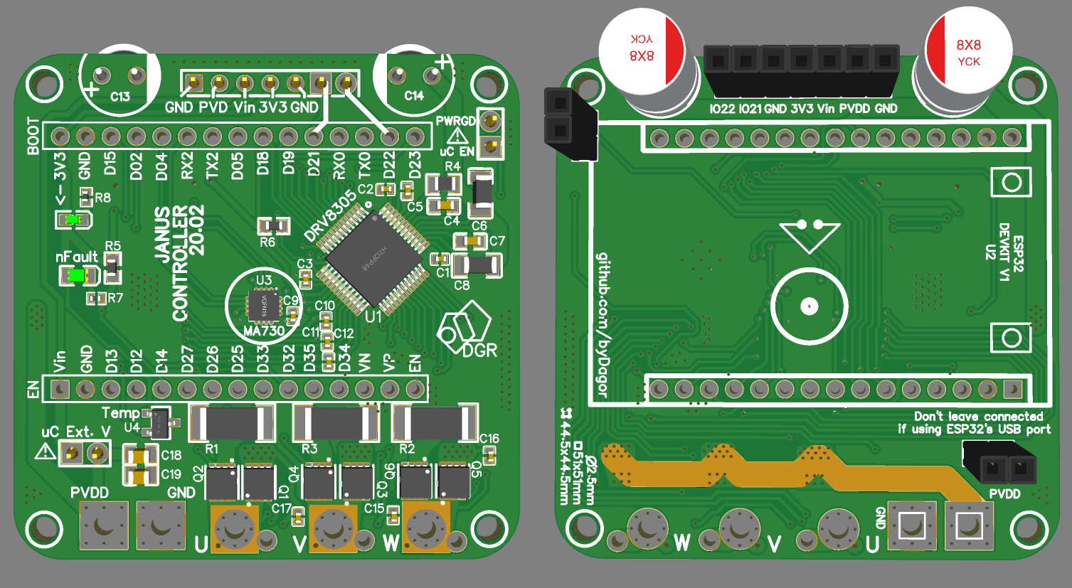
  • Encoder’s SPI bus connected
  • Moved encoder to the center of the board
  • Added capacitors 18 and 19
  • Differential current sensing routes with Kelvin connections

I will not order the new version soon, but I though I might just share the updated version if somebody feels like trying it out :slight_smile:

David

3 Likes

Thanks for the update. I plan to design a higher power board ( 24V, 40-60A maybe?) and seeing your design gives me ideas on how to proceed.

1 Like